_____________________________________________________________________________________
STI S.r.l. – Via Dei Caravaggi 15, 24040 Levate (BG) – ITALY www.imi-critical.com
Manual 5021, rev. 00 10/2015 – SC/VHS - 8 -
5.6 Installation
Warning:
Before proceeding with any Installation the following instructions must be
respected:
- Always wear protective clothing, gloves, and eyewear to prevent personal
injury.
- Use the lifting point foreseen on the actuator to move the actuator: if
different instructions are not well specified the lifting points foreseen on
the actuator must be used only to move the actuator.
- Check with your process or safety engineer for any additional measures
that must be taken to protect against process media.
5.6.1 Checks to be performed before installation
If the SC/VHS actuator is purchased separately, proceed as follows before assembling it onto the valve:
1) Check that the coupling dimensions of the actuator/coupling block flange and stem meet the
specified coupling dimensions.
2) Prepare the necessary tools for the assembly and setting of the unit.
3) Check that the outer surface of the actuator is free from dust and dirt.
4) Clean the actuator flange and remove anything that might prevent a perfect adherence to the
actuator/coupling block flange and joint especially all traces of grease.
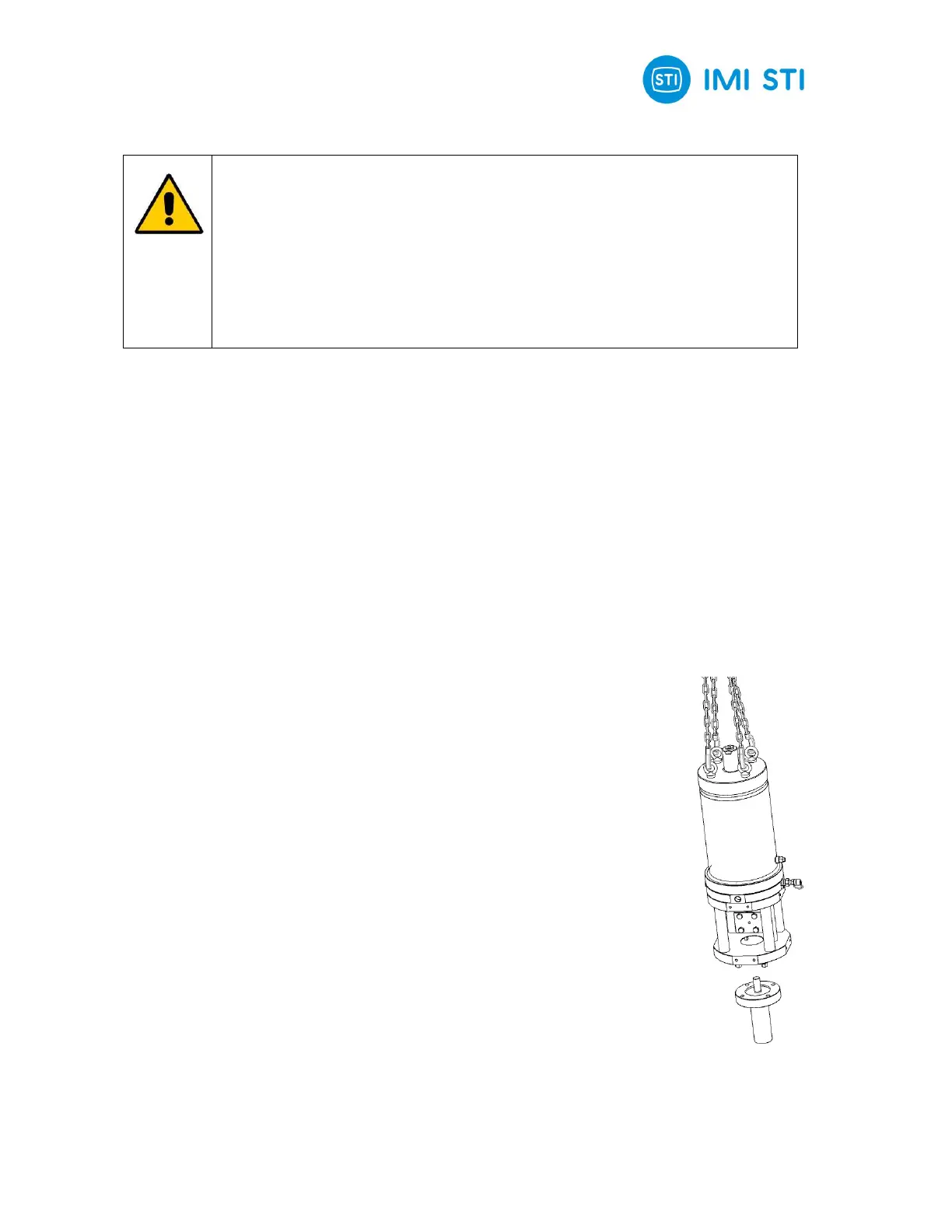
5.6.2 Assembling of the actuator on the valve
The actuator can be assembled on top of the valve flange by using the lifting eyelets installed on
hydraulic cylinder flange.
The assembly position of the actuator, with reference to the valve, must comply with the plant
requirements
To assemble the actuator onto the valve proceeds as follows:
Check that the coupling dimensions of the valve flange and stem, or of the
relevant extension, meet the actuator coupling dimensions (valve stem and
flange).
To make easier the assembly, the valve stem has to be in perfect vertical
position.
Disassemble the two halves of actuator shell joint (Fig. 7.2) by unscrewing
the retaining screws.
Lift the actuator by utilizing the proper lifting eyelets, and unscrew the nuts
and the stud bolts from the actuator pedestal.
Assemble the actuator onto the valve, and arrange it in its correct vertical
position proper to connection between valve stem and actuator cylinder rod.
Connect the valve stem and the actuator stem in their place inside into the
shell joint and refit the second half, tighten the screws fixing common
Screw the stud bolts into the actuator pedestal flange, and screw the nuts on
the stud bolts.
Tighten according to the nut size torque requirements.
Fig. 3
 Loading...