13
INSTALLERUSER
MAINTENANCE TECHNICIAN
1.10 AUXILIARY ACCESSORIES
CONNECTION.
3-way valve.
Audax TOP ErP units pilot a 3-way valve to
manage a DHW storage tank. e operation logic
provides that if DHW is requested by a storage
tank, the system controls a 3-way valve to direct
hot water only to the tank and operate maximum
capacity to supply water at 60°C (compatible with
the operating limits).
For operation, connect the 3-way valve between
PIN 18, N and terminal board 10 (refer to Fig.
1-12). PIN 18 (Line) and N (Neutral) provide
supply voltage to the valve (1ph ~ 230V, 2A max),
whereas PIN 10 has the control signal (1ph ~
230V, 2A max).
If a spring check valve is used, connect PIN 10
and N only.
The signal to request DHW must be a Dry
Contact type (quality of contacts above 25mA @
12V), which closes the circuit between PIN 15
and 13 of the terminal board (refer to Fig. 1-12).
Attention: DHW request has priority over pro-
grammed operation, both with central heating
and cooling.
Frequency limitations.
To force the unit to operate at a lower maximum
frequency (to reduce noise), provide a poten-
tial-free contact switch (quality of contacts above
25mA @ 12V) between PIN 13 and 14 of the
terminal board (refer to Fig. 1-12). With a closed
contact, the unit operates with a lower maximum
frequency than standard mode; vice-versa, it
operates in standard mode.
For proper operation, you must rst congure
the relative parameter from the remote panel
(refer to Par. 3.2).
Maximum noise reduction is approximately
3dB at 75% maximum operation frequency of
the compressor.
Unit Stop signal.
e terminal board has a few signals available to
indicate special operating conditions or to stop
the external unit.
e signals available are:
• Alarm: an alarm status is indicated, which stops
the compressor (PIN: 5-N)
Additional water pump (ADD WP).
It is possible to connect an auxiliary water
pump through clamps 12 and N. Regulation is
as follows:
1) On or o according to the heat pump's main
pump. In the event of DHW input activation,
the pump is on if a system request is present;
Signal for an External Heat Source (EHS)
request.
Between PIN 4 and N of the terminal board (refer
to Fig. 1-12), an outlet is available (1ph ~ 230V,
2A max), which can be programmed by means
of the remote panel (refer to Par. 3.2).
Two dierent strategies are available according
to the outdoor air temperature value:
1) Switching the heat pump o and activating an
auxiliary heat source. is function is activated
if the outdoor air temperature is below the value
set by means of the remote panel (refer to Par.
3.2). In this zone, the heat pump switches o
while the auxiliary heating device is activated
according to the following logic:
• ON/OFF according to the set-point of the
water temperature.
2) Both the heat pump and auxiliary heating de-
vice are activated simultaneously if heat output
supplied by the heat pump is insucient. is
function is activated when the outdoor air
temperature is below the value set by means
of the remote panel (refer to Par. 3.2). In this
zone, the unit remains operating while the
auxiliary heating device only starts if the water
temperature drops below the set-point minus
5°C for 10 minutes, which can be congured
from the remote panel (refer to Par. 3.2). e
auxiliary heating device switches o when the
water set-point is reached.
N.B.: in the event in which DHW request is ac-
tivated (closed contact between PIN 13-15), the
heat pump starts again and the auxiliary heating
device switches o.
Attention: in the event in which any kind of
outdoor heat source is installed, you must
install a thermal switch on the water circuit in
order to protect the system from excessive water
temperature peaks. is safety device must be
immediately placed downstream of the auxiliary
heating device.
Outdoor alarm input.
On the terminal board's terminal 21 (refer to Fig.
1-12) it is possible to receive an alarm signal (po-
tential-free contact) from outside, which forces
the unit to switch o.
When the contact closes (between PIN 21 and
3), the entire system switches o (Unit o, water
pump o, alarm N° 2 on the GMC board). As
soon as the potential-free contact opens, the unit
restarts operation according to the last congu-
ration. is signal can be sent to dierent types
of external control systems and/or safety devices.
For example, in case of danger, the contact can
be closed by an alarm signal sent from an ex-
ternal safety device. is way, the external unit
switches o without restarting until the contact
opens again.
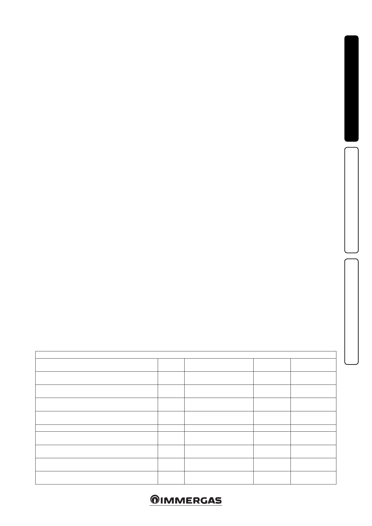
TERMINAL BOARD PIN
Audax TOP ErP
Description PIN Signal Limits
Menu installation
code 33AW-CS1B
DHW request 13 - 15
Input (contacts quality switch
>25mA@12V)
N.A. 153
Compressor Maximum Frequency Reduction 13 - 14
Input (contacts quality switch
>25mA@12V)
N.A. 5 - 6
3-way valve 10 - 18 - N
Output 230Vac (18-N: Supply
voltage, 10: signal)
1 ph ~ 230V, 2A N.A.
External Heat Source request 4 - N Output, Relay Contact 1 ph ~ 230V, 2A
106 - 148 - 150 - 151
- 152 - 154 - 155
Alarm 5 - N Output, Relay Contact 1 ph ~ 230V, 2A 147
Auxiliary Pump 12 - N Output, Relay Contact 1 ph ~ 230V, 2A 156 - 157
Alarm input 21 - 3
Input (contacts quality switch
>25mA@12V)
N.A. N.A.
On/O 6 - 3 Potential-free contact N.A. N.A.
Central Heating/Cooling 7 - 3 Potential-free contact N.A. N.A.

 Loading...