2-1
2-2
12:34 Fr 3 Jan 2014
Mode Menu
20.6
°C
Room set 21.0°C
67%
13°C
4
2
1
3
18
INSTALLERUSER
MAINTENANCE TECHNICIAN
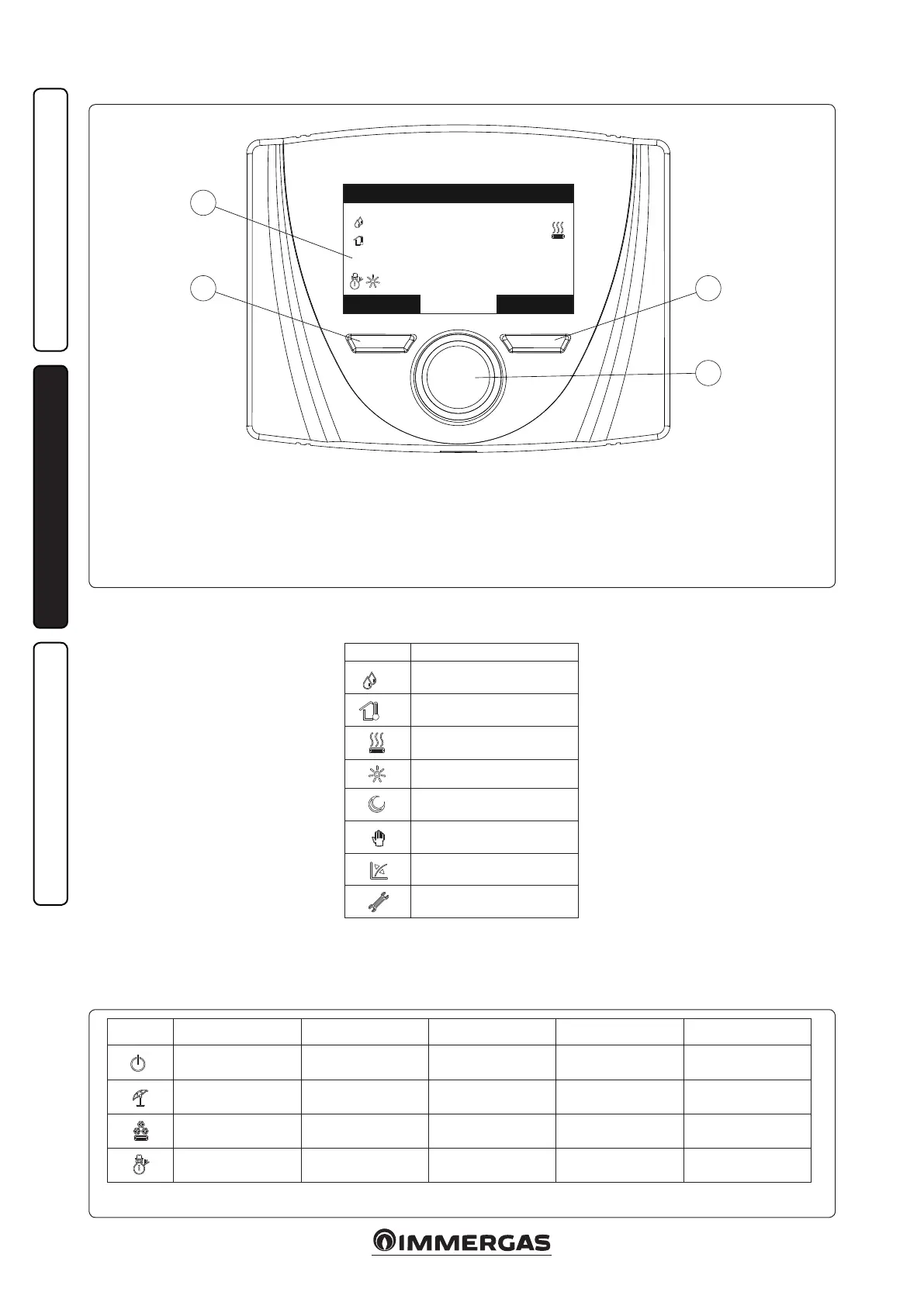
2.4 REMOTE PANEL.
Key:
1 - Main parameters switch with button to con-
rm and save data
2 - Le context button
3 - Right context button
4 - Display
State Description Domestic hot water Cooling Central heating Anti-freeze
Stand-by Disabled Disabled Disabled Enabled
Summer Enabled Disabled Disabled Enabled
Cooling Enabled Enabled Disabled Disabled
Winter Enabled Disabled Enabled Enabled
2.5 SYSTEM USE.
Once the device has been powered, it goes into
the status prior to switch-o. Press the “Modo”
(Mode) button to cyclically select the desired
mode amongst those available.
e current operating mode in use is displayed
by the relative icon at the bottom le corner
(Fig. 2-2).
Also, depending on the system's conguration,
the main screen displays various information
regarding the system, amongst which:
State Description
nn
Room humidity value (if hu-
midity probe is present)
nn
External temperature value
(external probe enabled)
Request for room central heat-
ing or cooling in progress
Comfort temperature operation
Economy temperature oper-
ation
Operation in manual mode
External probe enabled
Anomaly present
e lower part of the display shows the param-
eter that can be changed (it varies according to
conguration). Once the system has captured
the data (indicated with the text “Attesa dati...”
(Waiting for data...), it is possible to change the
value by turning the main switch and pressing to
conrm the parameter change.
e values that can be found according to the
conguration, are:
- Set room: denes the room zone temperature.
- Set ow: denes the system's ow temperature
to the zone.
- Oset ow: changes the operation curve of the
external probe.

 Loading...