1-4 1-5
1-7
1-6
1-8
600 051051
430
400
363
B
A
37
0
2
4
6
8
10
12
14
16
18
-5 0 5 10 15 20 25 30 35 40 45 5
8 - 12 - 16
6
10
15
20
25
30
35
40
45
50
55
60
65
-25 -20 -15 -10 -5 0 5 10 15 20 25 30
7
INSTALLERUSER
MAINTENANCE TECHNICIAN
1.4 INSTALLATION.
Before installation, make sure the base is solid
and laid at in order to prevent the onset of
anomalous noise. Depending on the dimensions
and minimum spaces requested, secure the base
well by using anchoring bolts (nuts and anchor-
ing bolts M10 x 2 pairs).
When the external unit must be installed in a
place exposed to strong wind, make sure opera-
tion of the fan is normal by using an anti-wind
protection.
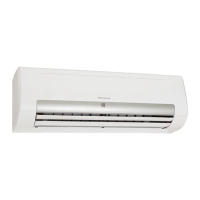
Cable passage opening procedure
To enable the cables to pass through, remove the
pre-cut part from where to pass the electrical
wires. Do not remove the unit's front panel so
that the pre-cut part can be easily punched. To
remove the pre-cut metal-sheet plate, punch the
3 connection points using a chisel and following
the guideline, then remove the part with pliers
(refer to Fig. 1-4). Aer opening the passage for
the cables, remove the trimmings and assemble
the supplied cable protection in order to protect
them.
Method used to remove the front panel
1) Remove the screws from the front panel (Refer
to Fig. 1-5).
2) Pull the front panel downwards using the
handle.
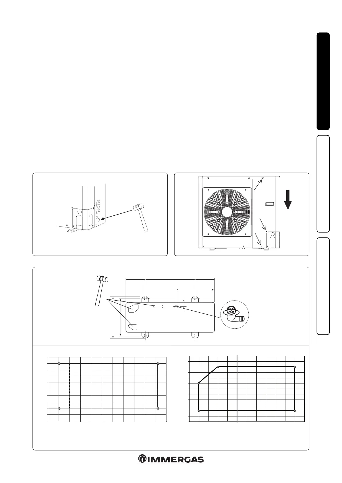
Condensate drain pipe and pre-cut holes in
the base
If draining is carried out through the drain pipe,
connect the drain tting (A, Fig. 1-6) and use a
drain pipe (internal diameter: 16 mm) available
on the market. In the event of installation in very
cold zones or zones subject to heavy snow where
the condensate drain pipe can freeze, check the
draining capacity of the pipe. Draining capacity
increases when the pre-cut holes at the base,
which collect condensate, are open (open the
pre-cut holes outwards with the aid of a hammer
with smooth edges (B, Fig. 1-6), etc.).
Operating limits
Cooling operation (Refer to Fig. 1-7):
X1 - Outdoor Air Temperature (°C)
Y1 - Outlet Water Temperature (°C)
N.B.: for Audax TOP 6 ErP units, consider a
minimum Outdoor Air Temperature of +5°C.
Central Heating Operation (Refer to Fig. 1-8):
X2 - Outdoor Air Temperature (°C)
Y2 - Outlet Water Temperature (°C)

 Loading...