10
STEEkW ed 01/06 EOLO Extra kW
Technical DocumentationTechnical Documentation
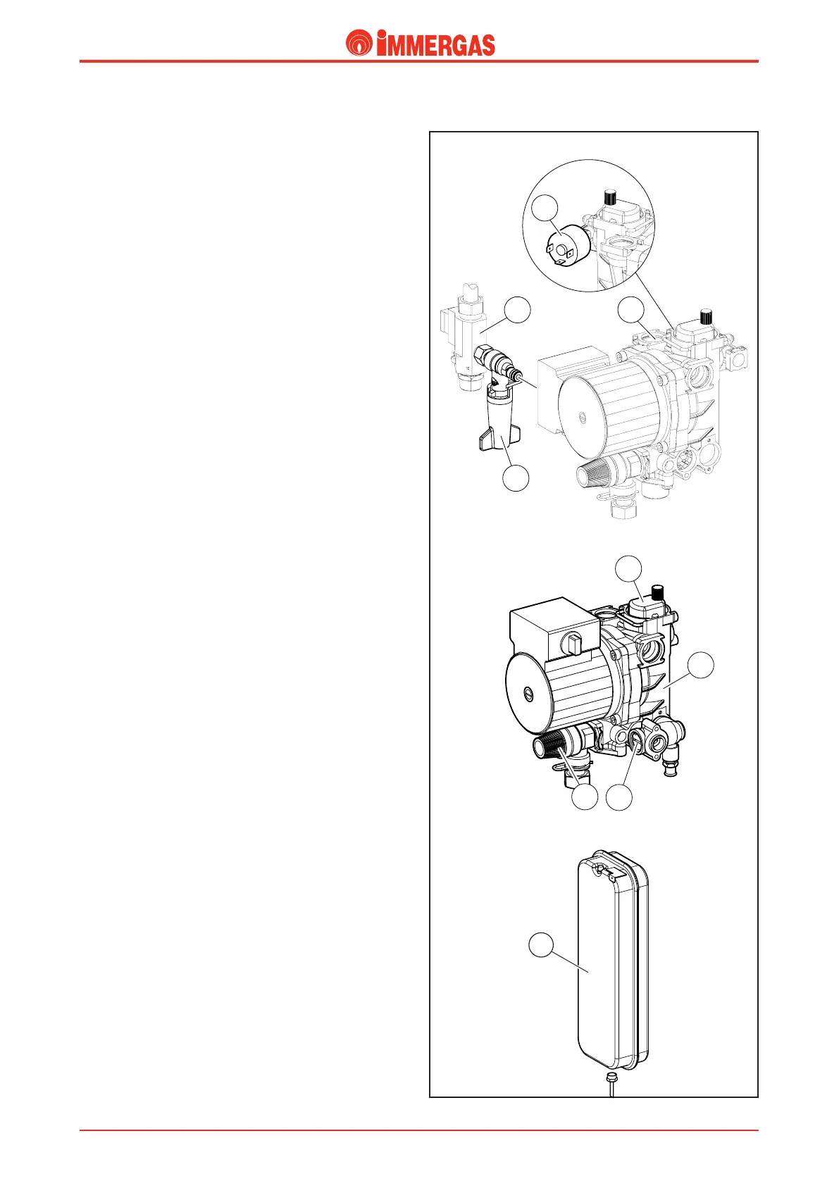
Safety devices and controls.
Automatic system by-pass (4).
is device guarantees circulation of water in the primary cir-
cuit (between delivery and return) even when this is prevented
by the system’s high resistance.
It is installed between the circulator body and the 3-way
unit.
It can be turned on or off by means of the screw (4) accessible
from the front; with the screwdriver slot horizontal the by-pass
is ON (open), with the screwdriver slot vertical the by-pass is
OFF (closed).
System filling device (7).
is device is a ball cock located between the boiler circuit
and d.h.w. cold water inlet and permits pressurisation of the
central heating system.
is unit is connected to the d.h.w. flow switch (6) by means
of a threaded fitting and to the pump unit (2) by means of
an O ring.
System pressure switch (5).
It reads the pressure inside the primary circuit.
It is housed on the circulator body (2) and coupled to a mi
-
croswitch that prevents the burner working when the pressure
measured is below 0.3 bar.
It prevents the primary exchanger from overheating.
Automatic air vent (1).
It automatically expels any gaseous substances from the boiler
circuit.
It is mounted on the circulator’s delivery side, directly on its
body (2).
3-bar safety valve (3).
is valve prevents the safety pressure being exceeded in the
primary circuit (3 bar).
It is fitted on the front of the circulator body (2) and fixed on
the outside with a fork.
When this valve triggers water exits from the boiler return
pipe.
System expansion vessel (8).
It compensates for variations in volume as a result of the water
heating which also limits pressure variations.
It has an 8-litre capacity (5.1 useful litres) and a 1.0 bar preload
pressure.
It is located on the right of the boiler alongside the sealed
chamber and is connected to the cold water inlet manifold
by a copper pipe.
8
 Loading...


