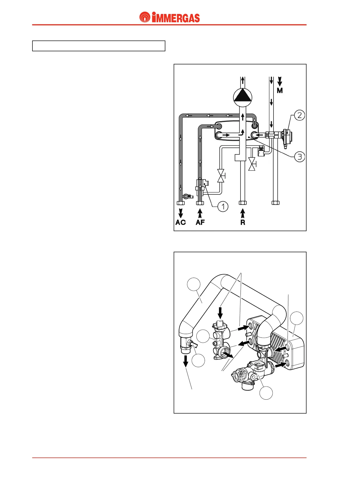
Operation.
When domestic hot water is drawn cold water flows inside
the d.h.w. flow switch (1) which closes the electrical contact
coupled to it (see the electrical circuit).
As a result, the integrated board starts the d.h.w. priority phase
that ignites the burner and, if there’s an ongoing central heating
request, switches the 3-way diverter valve (2) moving it into the
working position (see operation of the hydraulic 3-way valve).
is causes the delivery pipe (M) to close and simultaneously
the passage opens to the d.h.w. exchanger (3).
In this way circulation in the central heating system is preven-
ted while it is allowed in the plate exchanger, inside which the
domestic cold water absorbs the heat from the primary circuit
water (see d.h.w. exchanger).
So in this phase, central heating is off, domestic hot water
having priority.
e water/water heat exchange occurs inside the d.h.w. exchan
-
ger (3) which is secured to the d.h.w. inlet (1) and outlet (2)
body with screws.
e top of the body on the left allows cold domestic water to
enter, while at the bottom it allows primary circuit return.
In the same way, the top part of the body on the right allows
the outlet of domestic hot water while at the bottom it allows
primary circuit delivery.
Secondary circuit (D.h.w. Circuit).
Cold water
inlet
Primary circuit
delivery
Primary
circuit return
D.h.w. outlet
D.h.w. outlet
 Loading...


