17
STEEkW ed 01/06 EOLO Extra kW
Technical Documentation
Technical Documentation
Intake and outlet systems.
(see the intake and outlet terminal instructions).
e EOLO Extra kW boiler is designed for connecting the
couple-on air intake/outlet pipes and can be installed indoors
or outdoors in the open or in a partly sheltered location in the
following configurations:
Outdoors (in the open):
- room-sealed fan-assisted with direct air intake (type C)
utilising a cover kit;
Outdoors (in a partly sheltered location):
- room-sealed fan-assisted (type C) using the vertical or ho-
rizontal concentric kits, keeping the side plates on and not
having to use the top cover kit.
Indoors:
- fan-assisted with open chamber (type B) using the cover
kit;
- room-sealed fan-assisted (type C).
As far as concerns the head losses of each accessory, the various
combinations that can be created and the position of the
flue shutter which depends on the length of the pipes, see
the instructions for the air intake/outlet terminals (boiler
instruction manual).
e coupling of the accessories (curves, extensions, terminals)
is the push-fitting type and sealing is ensured by silicon lip
seals.
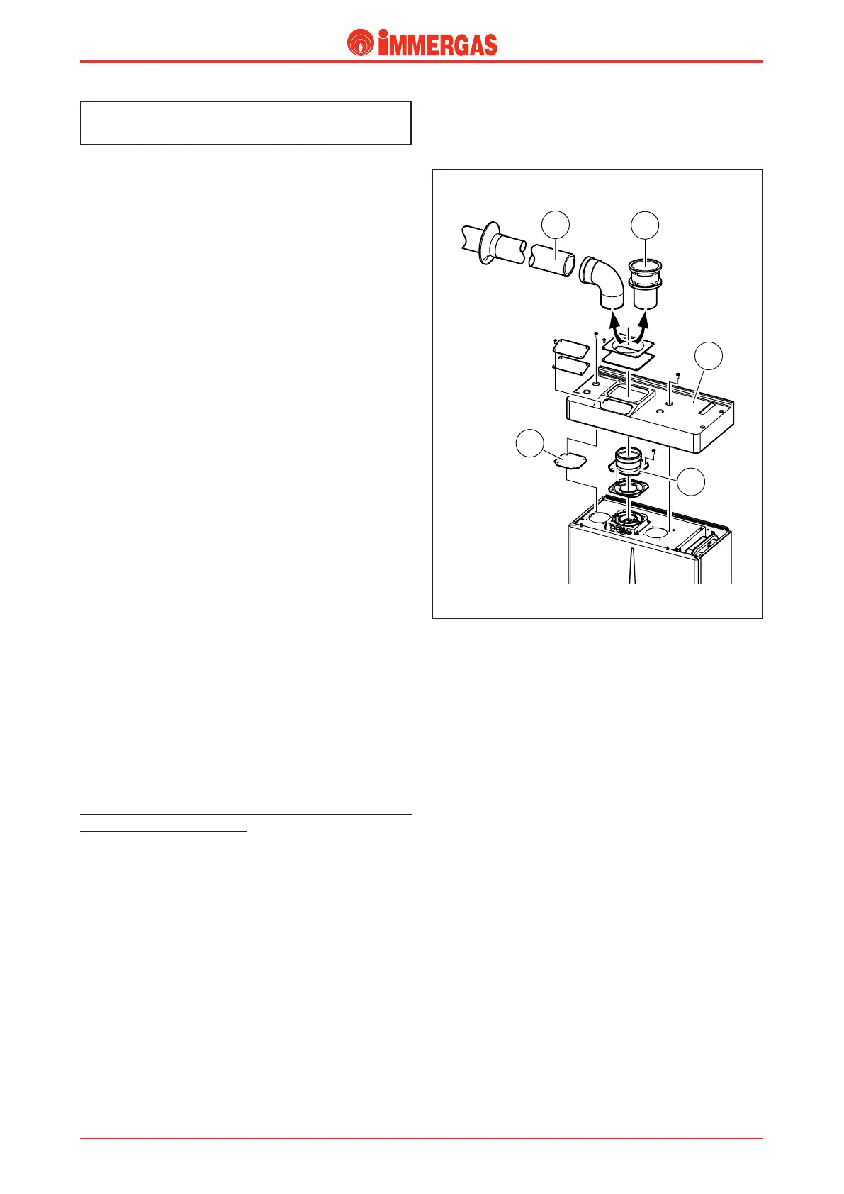
Room sealed fan assisted configuration with di-
rect air intake (type C) for outdoor installation
in the open (see figure on right).
By using the cover (1), positioned on top of the sealed chamber,
the boiler can be installed outdoors in the open.
Intake.
e two plates (3) – closing the holes at the top of the sealed
chamber – have to be removed in order to mount the cover
(1).
Combustion air is taken directly from the environment,
exploiting the gap between the bottom of the cover (1) and
the top of the boiler.
Note
: in the 28 kW version it is compulsory to cover the left
intake hole with the plate (3).
Outlet.
A flange (2) is used for coupling the 80 mm diameter outlet pi
-
pes, used in the split systems. You can have either a horizontal
(A) or vertical (B) outlet depending on the accessories used.
To avoid condensate problems, the outlet pipe should be li-
mited to 5 straight metres for normal pipes and 12 straight
metres for insulated pipes.
Maximum permitted length is 12 straight metres.
To ensure the boiler works properly with this kit, the flue
shutter needs to be adjusted on reference “5” (see boiler in-
struction manual).
Fan-assisted with open chamber (type B) con-
figuration for indoor installation (see figure
above).
e cover kit described previously is used. By removing the
side plates from the sealed chamber, air is taken in directly
from the room where the boiler is installed.
Fumes are discharged through 80 diameter pipes in a single
flue or directly outside.
Room-sealed fan-assisted (type C) configura-
tion.
(See EOLO Maior kW)
Outlet.
(See EOLO Maior kW)
Intake.
(See EOLO Maior kW)
Intake and Outlet kit.
(See EOLO Maior kW)
 Loading...


