18
STEEkW ed 01/06 EOLO Extra kW
Technical DocumentationTechnical Documentation
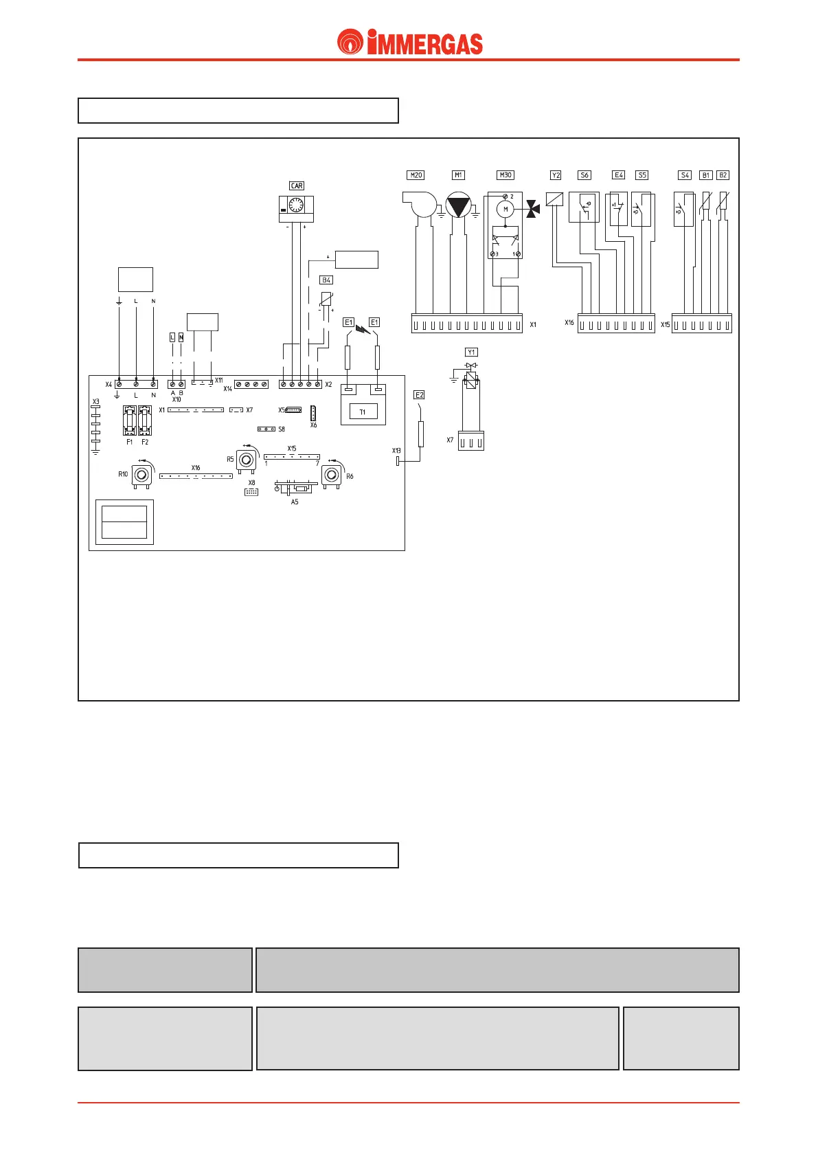
Electrical circuit.
EOLO Extra kW electrical circuit is controlled 100% by a mi-
croprocessor controlled p.c.b. that controls all boiler functions
together with the CAR control panel.
Some of the control and safety devices operate at mains voltage
(230 Vac) while others at low voltage.
Legend:
A5 - CAR interface board
B1 - Delivery probe
B2 - D.h.w. probe
B4 - External probe (optional)
CAR - Remote control
CZ - Zone control unit (optional)
E1 - Ignition electrodes
E2 - Detection electrode
E4 - Safety thermostat
F1 - Line fuse
F2 - Neutral fuse
M1 - Boiler circulator
M20 - Fan
M30 - 3-way valve
R5 - D.h.w. temperature trimmer
R6 - Central heating trimmer
R10 - Main selector switch
S4 -
D.h.w. flow switch
S5 - System pressure switch
S6 - Flue pressure switch
S8 - Gas type selector switch
T1 - Ignition transformer
Y1 - Gas valve
Y2 - Gas valve modulator
230 V AC circuit.
Safety devices and controls.
is detects ignition of the burner by whose flame it is covered.
It is connected to the integrated board.
Detection electrode
(E2)
ey interrupt power to the circuit when power input is over
3.15 A.
ey are fitted on the integrated board.
Line fuse (F1)
Neutral fuse
(F2)
Fuse
3,15 AF 250 V
 Loading...


