21
STEEkW ed 01/06 EOLO Extra kW
Technical Documentation
Technical Documentation
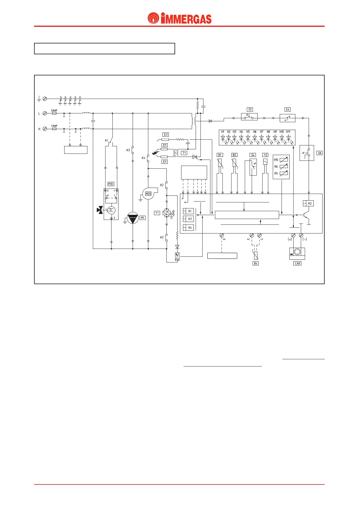
Electrical circuit.
Central heating phase.
Operating with the Remote Control.
e Remote Control (CAR) is enabled when the main selector
switch (R10) is in the “ON” position.
If the conditions found by the Remote Control (CAR) require
switching on in the central heating mode (the CAR’s SUM/WIN
selector on WINTER, central heating temperature setting higher
than what the heating delivery sensor (B1) measures, request for
the hourly programmer, room temperature setting higher than the
temperature measured), the integrated board powers the boiler
circulator (M1) by means of the K3 relay and, by means of the
K1 relay’s contact, powers the motor (M) of the 3-way valve
(M30) which keeps working until limit switch “3” opens when
the central heating position is reached.
In the meantime, if the flue pressure switch (S6) contact is
idle “NC”, the adjustment circuit powers the fan (M20) by
means of relay K4.
If the system pressure switch (S5)contact is closed (the pressure
measured in the primary circuit is higher than the minimum
value), with the enable of the safety thermostat (E4) and con-
sequent switching over of the flue pressure switch to “NO”
(S6) and if the temperature measured by the NTC delivery
probe (B1) is below that set with the Remote Control (CAR)
heating potentiometer, the integrated board excites the request
relay K2 causing the 2 contacts to close and in so doing the
ignition cycle starts, first controlling the ignition electrodes
(E1) and then both gas valve coils (Y1).
Burner ignition is detected by the integrated board via the
ionisation electrode (E2).
Operating with the Room ermostat.
Note: If the room thermostat is installed the CAR must be
disconnected from the electricity and the room thermostat
connected to terminals “40” and “41” of the X14 connector
on the integrated board.
e central heating mode is enabled when the main selector
switch (R10) is in the “PROG” position.
When the room thermostat contact closes the integrated board
powers the boiler circulator (M1) by means of the K3 relay
and burner ignition is as described above.
Note: Each time the thermostat turns off when the set tempe
-
rature is reached, the integrated board stops the burner working
in the central heating mode for the length of time set with the
board parameters (see integrated board operation).
 Loading...


