22
STEEkW ed 01/06 EOLO Extra kW
Technical DocumentationTechnical Documentation
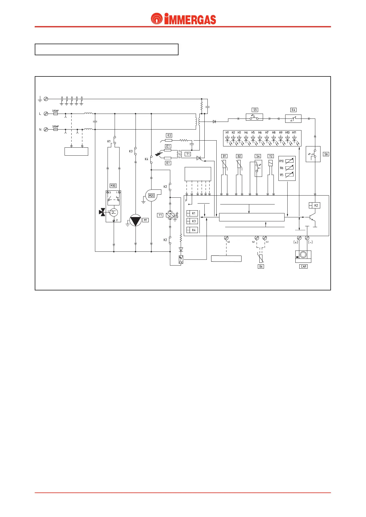
Electrical circuit.
Domestic hot water phase.
Operation.
e Remote Control (CAR) is enabled when the main selector
switch (R10) is in the “ON” position.
By running off some domestic hot water, the contact of the
d.h.w. flow switch (S4) closes and, if the temperature measured
by the d.h.w. NTC probe (B2) is less than the temperature set
on the control panel of the CAR , the integrated board powers
the boiler circulator (M1) by means of relay K3 and, by de-
viating the contact of relay K1, powers the motor (M) of the
3-way diverter valve (M30) that continues working until limit
switch “1” opens when the d.h.w. position is reached.
In the meantime, if the flue pressure switch (S6) contact is
idle “NC”, the adjustment circuit powers the fan (M20) by
means of relay K4.
If the system pressure switch (S5) contact is closed (the pressure
measured in the primary circuit is higher than the minimum
value), with the enable of the safety thermostat (E4) and con-
sequent switching over of the flue pressure switch to “NO”
(S6) the board closes the contact of the request relay K2 which
allows the ignition cycle to start, first controlling the ignition
electrodes (E1) and then both gas valve coils (Y1).
Burner ignition is detected by the integrated board via the
ionisation electrode (E2).
 Loading...


