23
STEEkW ed 01/06 EOLO Extra kW
Technical Documentation
Technical Documentation
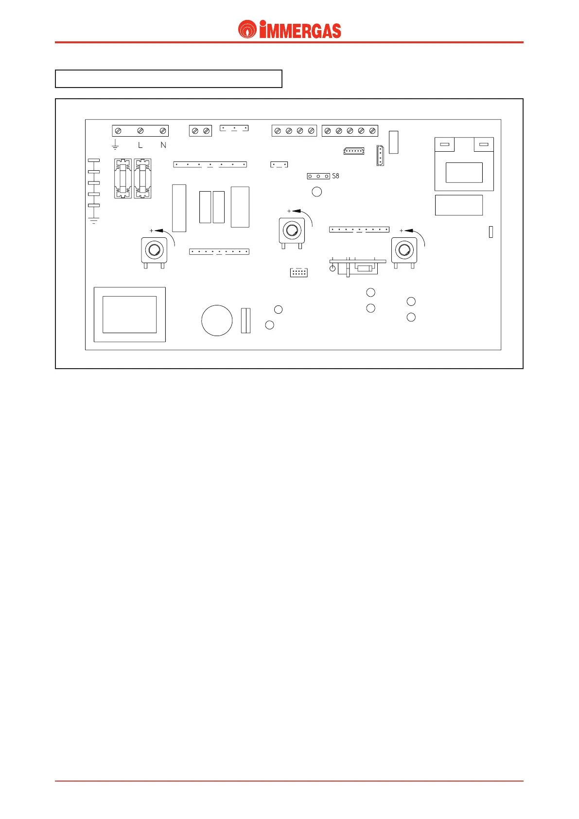
Integrated board.
Inside the boiler’s panel is a microprocessor controlled p.c.b.
that controls the appliance’s electrical devices, sees to the linear
modulation of burner output and, by means of LEDs, shows
the operating status of the appliance, signalling if any of its
safety devices have triggered.
e same board is used on all models, whether they are the
conventional flue or airtight chamber type (NIKE/EOLO
Maior kW, EOLO Extra kW, EOLO Extra 32 kW X, EX-
TRA Intra kW, EXTRA Intra 32 kW X). It automatically
recognises the different boiler operating types by means of
the appliance’s wiring.
e integrated board is always powered regardless of what
position the main selector switch (R10) is in.
e board executes a periodical self-check to make sure it is
working properly. During the central heating functioning
mode or with the boiler in Stand-by, this function is activated
every 18 hours from the last boiler check/powering. During
the d.h.w. functioning mode, this self-check starts within
10 minutes from the last time water was drawn and lasts 10
seconds.
NOTE: the boiler stops working (together with indications)
during the self-check operation.
Operation.
Central heating request.
e Remote Control (CAR) is enabled when the main selector
switch (R10) is “ON”.
If the conditions found by the Remote Control (CAR) require
switching on in the central heating mode the integrated board
powers the boiler circulator (M1) by means of the K3 relay
and, by means of the K1 relay’s contact, powers the motor (M)
of the 3-way valve which keeps working until limit switch “3”
opens when the central heating position is reached.
In the meantime, if the flue pressure switch (S6) contact is
idle “NC”, the adjustment circuit powers the fan (M20) by
means of relay K4.
If the system pressure switch (S5) contact is closed (the pressure
measured in the primary circuit is higher than the minimum
value), with the enable of the safety thermostat (E4) and con
-
sequent switching over of the flue pressure switch to “NO”
(S6) and if the temperature measured by the delivery probe
(B1) is below that set with the Remote Control (CAR) heating
potentiometer, the integrated board excites the request relay
K2 causing the 2 contacts to close which lets the ignition
cycle start.
During the first few seconds from when the gas valve (Y1) was
powered, the current to the modulation coil (Y2) is limited to
the predefined soft ignition current.
Subsequently, the burner goes to the minimum set value by
setting the “Minimum central heating power*” parameter and
then reaches the maximum set value (if requested) by setting
the “Maximum central heating power*” parameter in a time
determined when setting the “Central heating timer ramp*”
parameter.
After this the signal varies in a way directly proportionate to
the difference between the temperature set with the Remote
Control (CAR) central heating potentiometer and the tempe-
rature measured with the delivery probe (B1).
When the set temperature is exceeded (+5°C) the relay K2
contact opens and the burner switches off. Reignition time
depends on how the “Central heating ignition timer*” para-
meter is set.
Each time the burner is switched off the fan continues working
for 30 seconds and the pump for 150 seconds.
FUSES
MAIN SELECTOR SWITCH
TRANSFORMER
NAT-LPG
D.H.W.
CENTRAL
HEATING
 Loading...


