30
STEEkW ed 01/06 EOLO Extra kW
Technical DocumentationTechnical Documentation
Programming the integrated board.
e EOLO Extra kW boiler is designed for programming some
operating parameters if wanted.
By modifying these parameters the boiler can be adapted to
meet one’s specific requirements.
To access the programming phase you have to put the main
selector switch on Reset for 15 to 20 seconds; upon activation
LED 1 starts flashing and will continue to do so throughout
programming.
At this point, put the main selector switch back on "PROG"
position.
When the programming phase is activated, the first level is
accessed where it is possible to choose the parameter to set.
is one is indicated by the fast flashing of one of the LEDs,
between 2 and 11, simultaneously with LED 1.
Selection is made by turning the "SELEZIONE PARA-
METRI" knob (13).
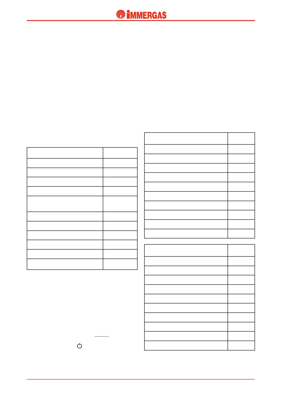
For the association of the LED to the respective parameter,
see the following table:
List of parameters
LED flashing
(fast)
Minimum heating output
LED 2
Maximum heating output
LED 3
Central heating ignitions timer LED 4
Central heating output supply ramp LED 5
Central heating ignitions delayed due
to room thermostat or Remote Control
requests
LED 6
Domestic hot water thermostat
LED 7
Circulator operation
LED 8
Operating gas
LED 10
Relay 1 operation
LED 11 e 2
Relay 2 operation
LED 11, 2 and 3
Relay 3 operation
LED 11, 2, 3
and 4
Once you have chosen the parameter to change confirm selec-
tion by temporarily turning the main selector switch round to
RESET until the LED relative to the parameter switches off
and then release it.
When the ok has been given for the selection, go to the second
level where the value of the parameter selected can be set.
e value is indicated by the slow flashing of one of the LEDs
- 2 to 11 - together with the flashing of LED 1.
e value is selected by turning the "MODIFICA PARAME-
TRI" knob (14).
To exit the programming mode, do nothing for 30 seconds
or, if you are on the “parameter setting” level, put the main
selector switch on position .
For the association of the LED to the value, see the following
tables:
Heating output.
e boiler is made and calibrated in the cen-
tral heating phase at nominal output. In addition, it features
an electronic adjustment that adapts boiler potential to the
home’s actual heating requirements.
is means that the boiler works normally in a variable field
of gas pressures, ranging from minimum to maximum output
depending on the system’s heating load.
NOTE:
selection of the “Minimum heating output” and
“Maximum heating output” parameters, when there is a cen-
tral heating request, allows boiler ignition and powering of
the modulation with current equal to the value of the relative
parameter selected.
Minimum heating output
(continuous variation)
LED flashing
(slow)
0% Imax. (Standard setting)
LED 2
7% Imax.
LED 3
14% Imax.
LED 4
21% Imax.
LED 5
28% Imax.
LED 6
35% Imax.
LED 7
42% Imax.
LED 8
49% Imax.
LED 9
56% Imax.
LED 10
63% Imax.
LED 11
Maximum heating output
(continuous variation)
LED flashing
(slow)
0% Imax.
LED 2
11% Imax.
LED 3
22% Imax.
LED 4
33% Imax.
LED 5
44% Imax.
LED 6
55% Imax.
LED 7
66% Imax.
LED 8
77% Imax.
LED 9
88% Imax.
LED 10
100% Imax. (Standard setting)
LED 11
 Loading...


