C
83
C
43
21
1
4
7
9
5
5
6
7
8
3
2
S
A
C
53
* - C
83
22
23
16
INSTALLERUSERMAINTENANCE TECHNICIAN
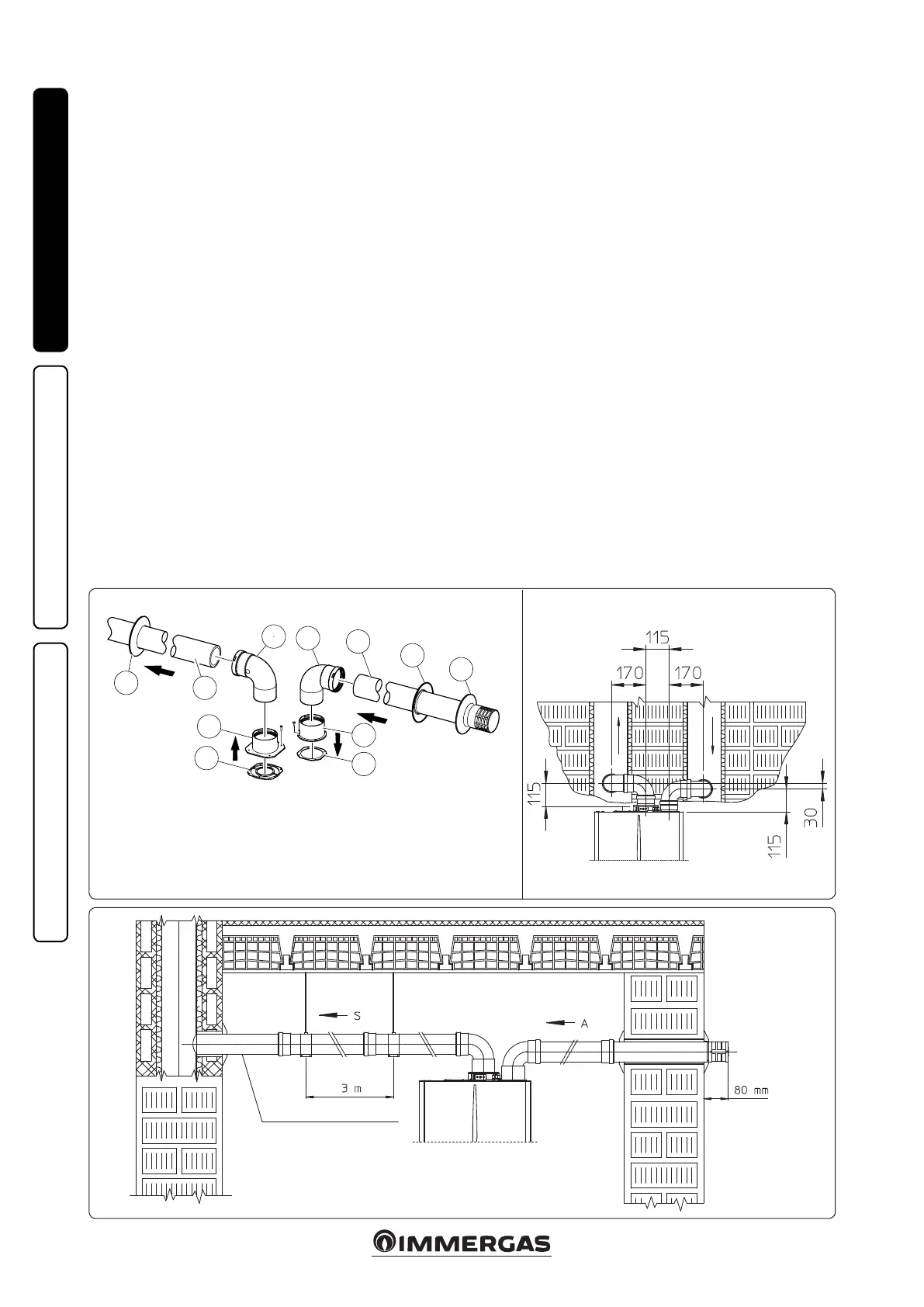
e kit includes:
N° 1 - Exhaust gasket (1)
N° 1 - Flange gasket (2)
N° 1 - Female intake ange (3)
N° 1 - Female exhaust ange (4)
N° 2 - Bend 90° Ø 80 (5)
N° 1 - Intake terminal Ø 80 (6)
N° 2 - Internal wall sealing plates (7)
N° 1 - External wall sealing plate (8)
N° 1 - Exhaust pipe Ø 80 (9)
1.16 SEPARATOR KIT INSTALLATION.
Type C configuration, sealed chamber and
fan assisted.
Separator kit Ø 80/80. is kit allows air to come
in from outside the building and the exhaust to
exit from the chimney, ue or intubated duct
through divided ue exhaust and air intake pipes.
Combustion products are expelled from pipe (S)
(in plastic, so as to resist acid condensate). Air is
taken in through duct (A) for combustion (this
is also in plastic). e intake pipe (A) can be
installed either on the right or le hand side of
the central exhaust pipe (S). Both ducts can be
routed in any direction.
• Kit assembly (Fig. 21): install ange (4) on
the central hole of the indoor unit, position-
ing gasket (1) with the circular projections
downwards in contact with the indoor unit
ange, and tighten using the hex screws with
at tip contained in the kit. Remove the at
ange present in the lateral hole with respect
to the central one (according to needs) and
replace it with the ange (3), positioning the
gasket (2) already present on the heat generator
and tighten using the supplied self-threading
screws. Fit the male side (smooth) to the bends
(5) in the female side of the anges (3 and 4).
Fit the intake terminal (6) with the male side
(smooth) in the female side of the bend (5) up
to the end stop, ensuring that the internal and
external wall sealing plates are tted. Fit the
exhaust pipe (9) with the male end (smooth)
to the female end of the bend (5) up to the end
stop; making sure that the internal wall sealing
plate has been tted, this will ensure sealing and
joining of the elements making up the kit.
• Installation clearances (Fig. 22). e minimum
installation clearance measurements of the Ø
80/80 separator terminal kit have been stated
in some limit conditions.
• Extensions for separator kit Ø 80/80. The
maximum vertical straight length (without
bends) that can be used for Ø 80 intake and
exhaust pipes is 41 metres, regardless from
whether they are used for intake or exhaust.
e maximum horizontal straight length (with
bend in suction and in exhaust) that can be
used for Ø 80 intake and exhaust pipes is 36
metres, regardless from whether they are used
for intake or exhaust. Please note the type of
installation C
43
must be done with a natural
draught ue.
N.B.: to favour the removal of possible conden-
sate forming in the exhaust pipe, tilt the pipes
towards the indoor unit with a minimum slope
of 1.5% (Fig. 23).
* to complete C
53
conguration, also provide for a roof discharge terminal. e
conguration on walls opposite the building is not allowed.
minimum slope 1.5%

 Loading...