C
33
C
33
C
33
C
33
7
4
6
5
1
2
3
1
2
3
4
5
6
7
17 18
19 20
15
INSTALLERUSERMAINTENANCE TECHNICIAN
e Kit includes:
N° 1 - Gasket (1)
N° 1 - Female concentric ange (2)
N° 1 - Wall sealing plate (3)
N° 1 - Aluminium tile (4)
N° 1 - Int./exhaust concentric pipe Ø
60/100 (5)
N° 1 - Fixed half-shell (6)
N° 1 - Mobile half-shell (7)
e adaptor kit includes:
N° 1 - Gasket (1)
N° 1 - Adapter Ø 80/125 (2)
e Kit Ø 80/125 includes:
N° 1 - Wall sealing plate (3)
N° 1 - Aluminium tile (4)
N° 1 - Fixed half-shell (5)
N° 1 - Mobile half-shell (6)
N° 1 - Concentric intake-exhaust
terminal Ø 80/125 (7)
e remaining kit components
must not be used
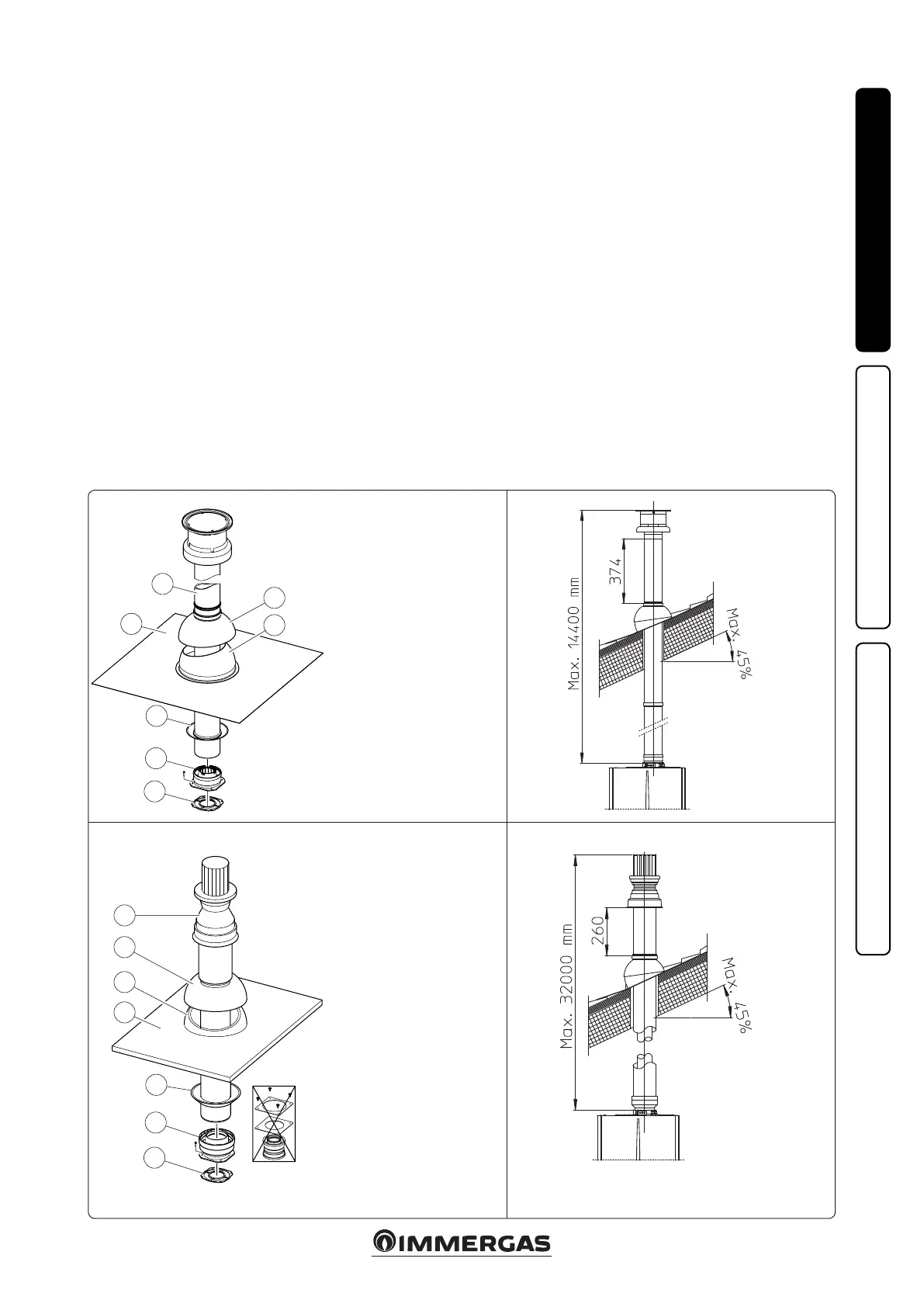
1.15 CONCENTRIC VERTICAL KIT
INSTALLATION.
Type C configuration, sealed chamber and
fan assisted.
Concentric vertical intake and exhaust kit. is
vertical terminal is connected directly to the
outside of the building for air intake and ue
gas exhaust.
N.B.: the vertical kit with aluminium tile enables
installation on terraces and roofs with a maxi-
mum slope of 45% (approx 25°) and the height
between the terminal cap and half-shell (374 mm
for Ø 60/100 and 260 mm for Ø 80/125) must
always be observed.
Vertical kit with aluminium tile Ø 60/100.
Kit assembly (Fig. 17): install the concentric
ange (2) on the central hole of the indoor unit,
positioning gasket (1) with the circular projec-
tions downwards in contact with the indoor unit
ange, and tighten using the screws contained
in the kit.
Installation of the fake aluminium tile: replace
the tiles with the aluminium sheet (4), shaping
it to ensure that rainwater runs o. Position
the xed half-shell (6) on the aluminium tile
and insert the intake-exhaust pipe (5). Fit the
Ø 60/100 (3) concentric terminal pipe with the
male side (5) (smooth) into the ange (2) up to
the end stop; making sure that the wall sealing
plate has been tted (3), this will ensure sealing
and joining of the elements making up the kit.
N.B.: when the boiler is installed in areas where
very cold temperatures can be reached, a special
anti-freeze kit is available that can be installed as
an alternative to the standard kit.
• Extensions for vertical kit Ø 60/100 (Fig. 18).
e kit with this conguration can be extended
to a max. straight vertical length of 14.4 m,
including the terminal. This configuration
corresponds to a resistance factor of 100. In
this case specic extensions must be requested.
Vertical kit with aluminium tile Ø 80/125.
Kit assembly (Fig. 19): to install the kit Ø 80/125
one must use the anged adapter kit in order
to install the ue system Ø 80/125. Install the
anged adaptor (2) on the central hole of the
indoor unit, positioning gasket (1) with the cir-
cular projections downwards in contact with the
indoor unit ange, and tighten using the screws
contained in the kit. Installation of the fake alu-
minium tile: replace the tiles with the aluminium
sheet (4), shaping it to ensure that rainwater
runs o. Position the xed half-shell (5) on the
aluminium tile and insert the intake-exhaust
pipe (7). Fit the Ø 80/125 concentric terminal
pipe with the male side (smooth) to the female
side of the adapter (1) (with lip gaskets) up to
the end stop; making sure that the wall sealing
plate (3) has been tted, this will ensure sealing
and joining of the elements making up the kit.
• Extensions for vertical kit Ø 80/125 (Fig. 20).
e kit with this conguration can be extended
up to a max. length of 32 m including the ter-
minal. If additional components are assembled,
the length equivalent to the maximum allowed
must be subtracted. In this case specic exten-
sions must be requested.

 Loading...