C
13
13 14
C
13
16
5
4
3
1
2
1
2
3
4
5
6
C
13
15
C
13
14
INSTALLERUSERMAINTENANCE TECHNICIAN
e kit includes:
N° 1 - Gasket (1)
N° 1 - Concentric bend Ø 60/100 (2)
N° 1 - Int./exhaust concentric terminal Ø 60/100 (3)
N° 1 - Internal wall sealing plate (4)
N° 1 - External wall sealing plate (5)
e adaptor kit includes:
N° 1 - Gasket (1)
N° 1 - Adapter Ø 80/125 (2)
e Kit Ø 80/125 includes:
N° 1 - Concentric bend Ø
80/125 at 87° (3)
1.14 CONCENTRIC HORIZONTAL KIT
INSTALLATION.
Type C configuration, sealed chamber and
fan assisted.
is terminal is connected directly to the outside
of the building for air intake and ue gas exhaust.
e horizontal kit can be installed with the rear,
right side, le side or front outlet. For installation
with frontal outlet, one must use the xing plate
and a concentric bend coupling in order to ensure
sucient space to carry out the tests required by
law upon commissioning.
• External grid. Both the Ø 60/100 and Ø 80/125
intake/exhaust terminal, if properly installed, is
pleasant to look at on the outside of the build-
ing. Make sure that the external silicone wall
sealing plate is properly inserted in the wall.
N.B.: for proper system operation the terminal
with grid must be installed correctly ensuring
that, the "high" indication on the terminal is
observed during installation.
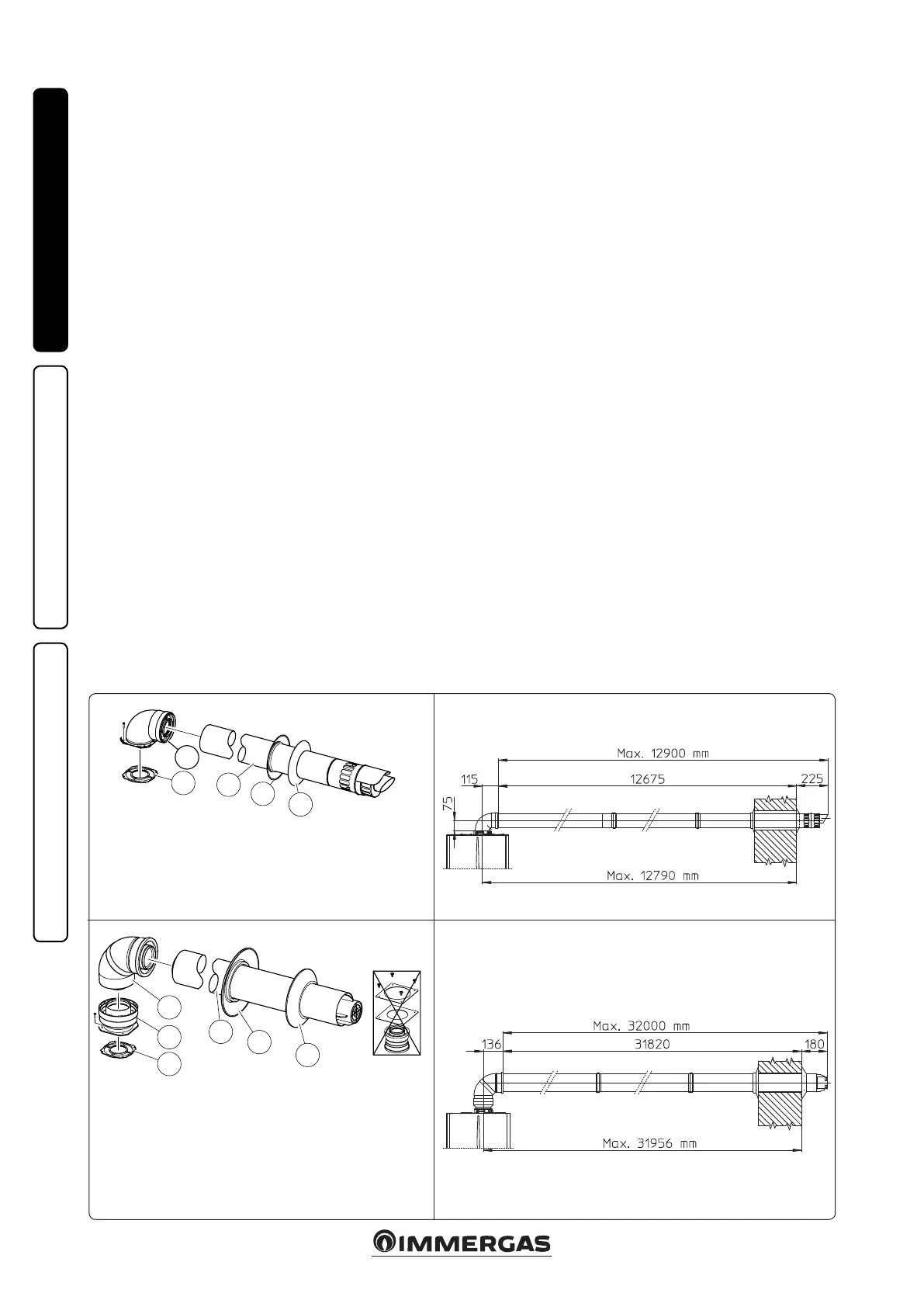
Horizontal intake-exhaust kit Ø 60/100. Kit
assembly (Fig. 13): install the bend with ange
(2) on the central hole of the indoor unit, posi-
tioning gasket (1) with the circular projections
downwards in contact with the heat generator
ange, and tighten using the screws present in
the kit. Fit the Ø 60/100 (3) concentric terminal
pipe with the male side (smooth) to the female
side of the bend (2) up to the end stop; making
sure that the internal and external wall sealing
plate have been tted, this will ensure sealing
and joining of the elements making up the kit.
• Extensions for Ø 60/100 horizontal kit (Fig.
14). e kit with this conguration can be ex-
tended up to a max. horizontal length of 12.9 m
including the terminal with grid and excluding
the concentric bend leaving the indoor unit.
is conguration corresponds to a resistance
factor of 100. In this case the special extensions
must be requested.
Immergas also provides a Ø 60/100 simplied
terminal, which in combination with its ex-
tension kits allows you to reach a maximum
extension of 11.9 metres.
Horizontal intake-exhaust kit Ø 80/125. Kit
assembly (Fig. 15): to install the kit Ø 80/125
one must use the anged adapter kit in order
to install the ue system Ø 80/125. Install the
anged adaptor (2) on the central hole of the
heat generator, positioning gasket (1) with the
circular projections downwards in contact with
the indoor unit ange, and tighten using the
screws contained in the kit. Engage the bend (3)
with the male side (smooth) to the end stop on
the adapter (1). Fit the Ø 80/125 (5) concentric
terminal pipe with the male side (smooth) to
the female side of the bend (4) (with lip seals)
up to the end top; making sure that the internal
(6) and external wall sealing plate (7) have been
tted, this will ensure sealing and joining of the
elements making up the kit.
• Extensions for Ø 80/125 horizontal kit (Fig.
16). e kit with this conguration can be
extended up to a max. length of 32 m, includ-
ing the terminal with grid and excluding the
concentric bend leaving the indoor unit. If ad-
ditional components are assembled, the length
equivalent to the maximum allowed must be
subtracted. In this case the special extensions
must be requested.
N° 1 - Concentric intake-ex-
haust terminal Ø 80/125
(4)
N° 1 - Internal wall sealing
plate (5)
N° 1 - External wall sealing
plate (6)
e remaining kit components
must not be used

 Loading...