R
M
1
2
18
18
19
19
20
20
6
7
8
9
9
10
12
13
14
12
16
17
4
15
5
5
21
11
3
* Components not present in the kit.
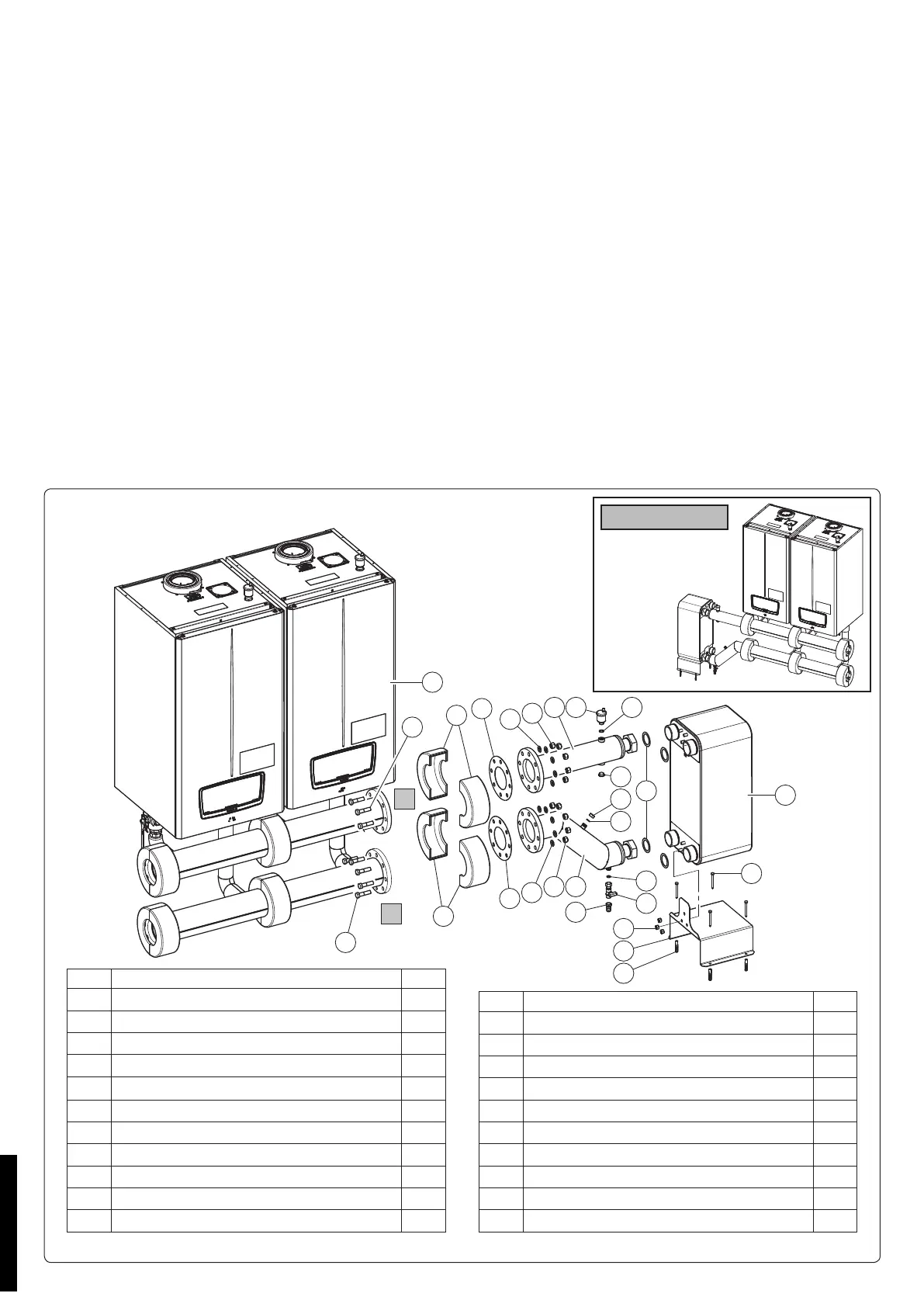
Mounting the plate exchanger for Victrix Pro 100-120-150 V2.
Assemble the automatic air vent valve (4) on the manifold (7) making sure to interpose the O-ring (3) and tighten the free connection
with the brass plug (17), making sure to interpose suitable sealing material such as oakum or similar.
Assemble the valve (13) and the hose connector (14) in sequence on the manifold (8), and on the free connection tighten the plug (16)
making sure to place the gaskets (12) in between.
Connect the manifold (8) to the return pipe (R) of the boiler (21), making sure to insert the gasket (9) and, using the screws (18), the
washers (20) and the nuts (19).
Secure the plate exchanger (6) to the exchanger support bracket (10) using the nuts (15).
Connect the manifold (8) to the plate heat exchanger (6), interposing the gasket (11).
Connect the manifold (7) to the delivery pipe (M) of the boiler (21), making sure to insert the gasket (9) and, using the screws (18), the
washers (20) and the nuts (19).
en connect the plate heat exchanger (6) to the manifold (7) placing the gasket (11) in between.
Position the insulation (5) on the delivery (M) and return (R) of the boiler (21).
Secure the exchanger support bracket (10) to the ground using the screws (1) and the respective plugs (2), as shown in Fig. 18.
Aer the 1st temperature test, check the tightness of all the pipes.
N.B.: e connections with caps 16 and 17 tted must be used for connections to the expansion vessel and for lling the boiler circuit
(for sizing the vessel, refer to the data table).
If assembling the kit with free outputs on the le side, perform the installation as shown in gure 19.
Attention: the VICTRIX PRO V2 boilers have an IPX5D electric insulation rating and can also be installed outdoors by means of the
relevant kits. However, if installed outdoors, the kit should be protected from the elements.
e boilers must be installed in the congurations and with their own original safety kits. e factory declines all liability whenever the
installer does not use the devices and approved original kits or uses them improperly.
18
Ref Kit components description Q.ty
1 HH screw 8x80 4
2 Plug 12x60 4
3 O.R. 18X2 Nitrile 70 SH. 1
4 Automatic air vent valve 1-2 mini 1
5 Insulation 4
6 100-plates-exchanger XB66LSB1100 1
7 Flow manifold 1
8 Return manifold 1
9 Gasket 2
10 Exchanger support bracket 1
11 75X55X2 mm gasket in Fasit So RG 4
Ref Kit components description Q.ty
12 18.5X11.5X2 AFM 34/2 gasket 2
13 Valve G 1-2 MF with tang 1
14 Roma type hose connection, female G1-2X15 1
15 HN nut M12 3
16 Cap 1-2 F hex key 23 mm 1
17 Kramer brass cap G 1-2 male 1
18* HH screw M16x65 16
19* HH nut M16 16
20* Washer 17x30x3 16
21* Boiler -
LEFT OUTLET
19
STD.010398/000
 Loading...