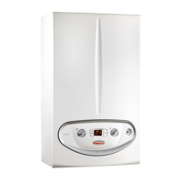
Do you have a question about the Immergas Victrix Zeus 25 and is the answer not in the manual?
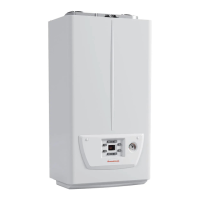
Key characteristics and technical specifications of the boiler unit.
Energy efficiency ratings for Victrix Zeus 25 and 32 models.
Physical dimensions and connection points for installation.
Identification and numbering of key internal boiler components.
Diagrams and details for electrical wiring of the unit.
Detailed diagram and key for the boiler's hydraulic system.
Description of the primary heat exchanger and its features.
Details on the pump group, its materials, and integrated components.
Functions and implications of using dual NTC temperature probes.
Performance curves for the circulator pump at different speeds.
Explanation of the modulating pump's operating modes and parameters.
Information on the stainless steel storage tank and its features.
Description of the 3-way valve motor's operation phases.
Details on the condensate syphon's components and maintenance.
Diagram of the combustion pathway and gas supply components.
Technical explanation of the SVG electronic gas valve.
How the system manages combustion air and gas ratio for efficiency.
Key benefits of the electronic combustion control system.
Overview and identification of controls on the boiler's panel.
Explanation of icons, indicators, and information shown on the display.
Description of boiler modes: Stand-by, Summer, Winter, and Off.
Detailed electrical wiring diagram for the Victrix Zeus 25 model.
Indications, safeties, and memory features of the electronic board.
Operation and activation of the automatic air vent function.
How to access and interpret the information menu parameters.
List of error codes, their anomalies, and potential causes.
Specific error codes related to the modulating pump and flue probe.
Steps to enter and navigate the parameter programming menus.
Parameters related to pump and relay settings.
Parameters for central heating and DHW temperature settings.
Parameters for hydraulic model and circulator settings.
Parameters for gas type and combustion regulation.
Parameter for defining flue pipe length and fan speeds.
Procedure for testing flue pipe length and setting parameter F0.
Process for verifying and calibrating the boiler's combustion performance.
Required technical equipment and mandatory conditions for startup.
Flowchart for the commissioning and calibration process.
Required calibration procedures after component substitution.
Steps to activate and perform a complete boiler calibration.
Procedure for calibrating nominal heat output based on CO2 values.
How to adjust CO2 levels if measured values are outside the limits.
Procedure for calibrating the boiler's intermediate power output.
Procedure for calibrating the boiler's minimum power output.
Steps to activate and perform a fast boiler calibration.
Overview of available accessories and optional kits for the boiler.
Configuration for integrating the boiler with a system manager and heat pump.
| Type | Condensing boiler |
|---|---|
| Output Power | 25 kW |
| Mounting | Wall-mounted |
| Max working temperature | 90°C |
| Electrical connection | 230V / 50Hz |
| NOx emissions | Class 6 |
| Fuel Type | Natural Gas |
| Water pressure | Max 3 bar |
