Do you have a question about the Immergas VICTRIX ZEUS Superior kW I and is the answer not in the manual?
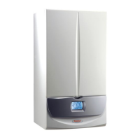
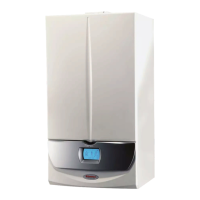
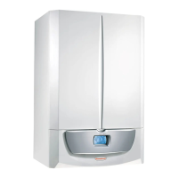
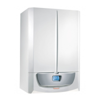
Overview of the boiler's primary characteristics and type approvals.
Description of the boiler's control panel, buttons, and display functions.
Visual representation of the boiler's hydraulic circuit and its components.
Explanation of the primary circuit's function and head-flow rate characteristics.
Detailed description and operation of the motorised 3-way valve.
Guarantees water circulation in the primary circuit, adjustable for system resistance.
Ball valve for pressurizing the central heating system.
Detects primary circuit pressure and prevents burner operation below 0.3 bar.
Automatically expels gaseous substances from the boiler circuit.
Prevents the primary circuit pressure from exceeding 3 bar.
Compensates for water volume variations due to heating.
Instructions for replacing key components of the GIM unit.
Description of storage tank, expansion vessel, anode, and probes.
Details on DHW recirculation kits and safety valve unit functions.
Description of the fan, Venturi pipe, burner, and gas valve.
Function and placement of ignition and detection electrodes.
Procedures for replacing the gas nozzle and burner.
Steps for removing the condensation module and flue hood.
Guide for replacing ignition and detection electrodes.
How to adjust nominal and minimum heat output for optimal performance.
Correct regulation of the air-gas ratio for optimal combustion.
Procedure for adapting the boiler to different gas types.
Description of flue gas flow, condensation, and related components.
Function and importance of the condensate drain trap.
Options for installing the boiler outdoors in partially protected areas.
Options for installing the boiler indoors with various flue kits.
Details on concentric and divided flue kits for installation.
Options for using 80mm rigid or flexible ducting systems.
Explanation of safety devices and loads in the 230V AC circuit.
Explanation of safety devices and controls in the low voltage circuit.
List of output signals and components in the low voltage circuit.
Operation in CH mode, including thermostat and remote control usage.
Operation in DHW mode, including temperature sensing and pump activation.
How the P.C.B. manages central heating requests and burner ignition.
Management of DHW, solar, anti-freeze, and deaeration functions.
Description of probes, switches, and remote control inputs.
List of output signals and components controlled by the P.C.B.
Overview of safety device actions like anti-block and fan speed monitoring.
Details on flue safety, circulation, and probe fault detections.
List and description of boiler operating states shown on the display.
Accessing and viewing boiler operating information.
Customising operating options and settings.
Technician access to advanced boiler configuration parameters.
Settings for pump speed, timing, and relay outputs.
Table of fault codes, their display, and corresponding Super CAR/Car display.
Technical specifications related to combustion performance and emissions.
Heat output and gas flow rate data for the 26 kW I model.
Heat output and gas flow rate data for the 32 kW I model.
List of optional accessories and their product codes.
Step-by-step guide for resolving issues in CH mode.
Step-by-step guide for resolving issues in DHW mode.
Troubleshooting steps for ignition failure errors.
Troubleshooting steps for overheating safety thermostat errors.
Troubleshooting steps for flue safety thermostat errors.
Troubleshooting steps for contact resistance issues.
Troubleshooting steps for flow probe anomalies.
Troubleshooting steps for low system pressure errors.
Troubleshooting steps for storage tank probe anomalies.
Troubleshooting steps for wiring configuration errors.
Troubleshooting steps for fan related anomalies.
Troubleshooting steps for parasite flame block errors.
Troubleshooting steps for return probe anomalies.
Troubleshooting steps for control panel button issues.
Troubleshooting steps for insufficient circulation errors.
Troubleshooting steps for remote control communication loss.
Troubleshooting steps for low power supply voltage errors.

