Do you have a question about the Immergas ZEUS Superior Series and is the answer not in the manual?
Table showing physical dimensions of the boiler models (Height, Width, Depth).
Diagram and labels detailing boiler pipe and electrical connection points (G, R, M, U, E).
Explains the boiler's primary circuit operation, heat absorption, and water circulation.
Ensures primary circuit circulation, adjustable via a screw for system resistance.
Used to pressurize the heating system; includes a one-way valve to prevent backflow.
Detects pump pressure difference, preventing burner operation on blockage.
Protects the circuit by preventing pressure from exceeding 3 bar.
Automatically expels air from the boiler circuit to maintain efficiency.
Compensates for water volume changes due to temperature fluctuations.
Details how the DHW circuit activates, circulates water through the coil, and prioritizes DHW.
Description of anode, polyphosphate metering unit, and recirculation kit for the storage tank.
Covers NTC sensor, max flow thermostat, safety valve unit, and expansion vessel for the tank.
Explains the function and activation of the Gaudium Magnum device for increased DHW flow.
Describes the valve's function in diverting primary circuit water for heating or DHW.
Overview of gas flow, air-gas mixing, and ignition process within the gas circuit.
Details the gas valve's main and modulation coils for gas pressure and flow control.
Describes the burner assembly, nozzles, ignition electrodes, and flame detection.
Instructions for setting maximum and minimum gas pressure on the SIT 845 valve.
Procedure for adapting the boiler to different gas types (Natural Gas/LPG) via kits and board settings.
Explains how combustion residues are conveyed and extracted by the fan and hood.
Details the points for sampling combustion air and flue gases.
Describes the pressure points used for measuring flue pressure switch signals.
Describes how the boiler connects to exhaust pipes using flanges, curves, and seals.
Details connection methods for extraction pipes using doubled or coaxial systems.
Overview of available kits and accessories for extraction and exhaust systems.
Details for the vertical concentric kit with 60mm exhaust and 100mm extraction pipes.
Details for the vertical concentric kit with 80mm exhaust and 125mm extraction pipes.
Description of the 80/80 coupling type separator kit for flue and extraction.
Details of the insulated 80/80 coupling type separator kit, including insulation.
Wiring diagram illustrating the main 230V AC power supply connections and components.
Overview of safety devices and their functions within the electrical circuit.
Details the boiler's central heating operation sequence when controlled by a room thermostat.
Describes the central heating operation sequence when using the remote control.
Details the boiler's operation sequence for domestic hot water (DHW) demand.
Explains DHW operation when the Gaudium Magnum switch is activated.
Covers central heating requests via room thermostat or remote control to the modulation board.
Describes the boiler's operation sequence in response to a domestic hot water request.
Explains the boiler's operation for antifreeze protection in central heating mode.
Details the chimney sweep function activated via the reset button for max heating output.
Description of NTC and PTC sensors used for temperature monitoring and control.
Input signals from safety devices (flame detection, pressure switches) to the control unit.
Inputs for main switch, remote control, room thermostat, and zone control unit.
Procedures for setting central heating and domestic hot water temperatures.
Settings for gas selection, heating power, pump operation, and soft ignition.
Safety features for circulator antilock and pump post-circulation operation.
Protection mechanisms for faulty sensors and overheating conditions.
Actions taken after burner switch-off, including combustion chamber washing.
Explains the function of DL1, DL2, and DL3 LEDs on the display card.
Details information shown on the boiler's display, including temperatures and error codes.
Step-by-step sequence for boiler operation in central heating mode.
Step-by-step sequence for boiler operation in domestic hot water mode.
Tables detailing burner gas flow rate and pressure for different heat outputs and gas types.
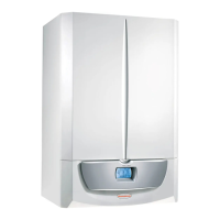
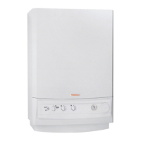
| Type | Condensing boiler |
|---|---|
| Installation | Wall-mounted |
| ErP Rating | A |
| Heat exchanger | Stainless steel |
| Output | 24 kW to 32 kW |
| Efficiency | Up to 98% |
| Fuel Type | Natural gas, LPG |
| Control System | Digital LCD display with remote control option |
| Warranty | 2 years |





 Loading...