19
STVZSkW ed 09/08 VICTRIX ZEUS Superior kW I
Technical Documentation
Technical Documentation
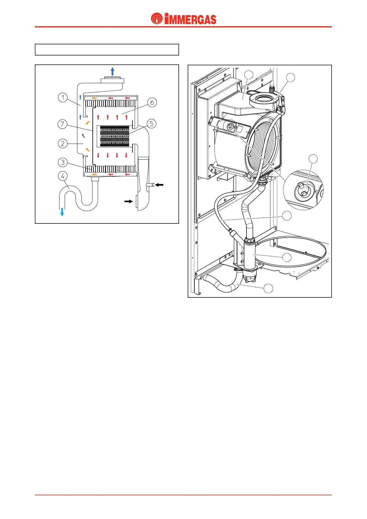
A ue safety thermostat is inserted onto the condensation
module (12), to protect the ue hood (1) and which intervenes
when the temperature detected on the condensation module
exceeds 110 °C.
Condensate drain trap (4).
Collects the condensate that forms during boiler functioning
from the bottom of the module.
Its outlet is connected to the draining pipe (11) towards which
the passage of water is allowed but not the passage of combu-
stion products, which could occur following obstruction of
the evacuation pipes.
e height of the column of water in the siphon is in fact
greater than the pressure detected inside the sealed chamber
(module) with the fan at maximum speed and the evacuation
pipes blocked at functioning limits.
is, however, prevents the draining of combustion products
into the sewers.
On commissioning combustion products may escape from
the exhaust pipe (11), which disappear after a few minutes
of functioning when the condensate has reached a sucient
height. If this should take too long, ll the siphon with water
manually (4).
Flue circuit.
Operation.
e functioning of the fan positioned at the entry of the air-
gas mixing pipe, guarantees the fan-assisted expulsion of the
combustion products (5).
ese directly hit the rst three elements (26 kW) or 4 (32
kW) of the primary heat exchanger inserted in the sealed
combustion chamber (6), which has a sheet steel section on
its base (7) that divides it from the condensation chamber (2)
and diverts the ow of combustion products to the outside
of the module.
In this way the ue gases, before entering the condensation
chamber (2), hit the fourth (26 kW) or 5th (32 kW) element
(3) of the heat exchanger inside which primary circuit return
water runs.
is cools the combustion products further and makes their
condensation easier before escape from the ue hood (1).
e water condensate formed inside the heat exchanger, in
the ue hood and also in the evacuation pipes ows into the
lower part of the module from where, before being discharged,
is conveyed into a trap (4). Any water formed in the intake
pipes is collected in a valley gutter (13) and by means of a
silicone pipe (10) is conveyed into the siphon (4) to then be
drained away.
Flue hood (1).
It is connected to the rear part of the condensation module
and conveys the combustion products towards the drain tting
present in the upper part of the appliance.
It is aected by the passage of combustion products and water
condensate formed inside it or in the exhaust pipes.
It is constructed in plastic, resistant to the corrosive eects of
the condensate and can work to a temperature of 130 °C (max.
ue temp with ow 85 °C = 78 °C).
Gas
Air
Condensate Drain
Flue exhaust

 Loading...