Chapter 7 Usage of Various Functions
7-
ో
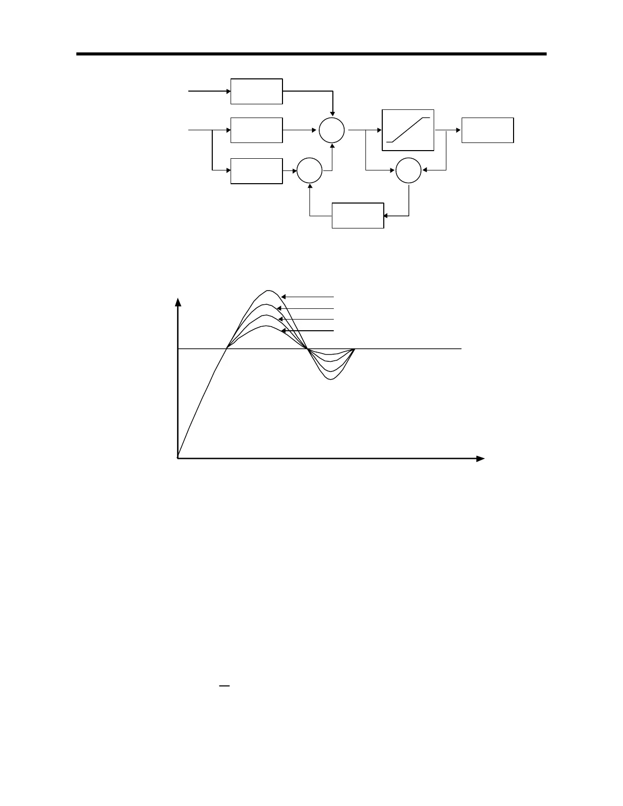
Fig. 2-13 The block diagram of anti-windup control system
Fig. 2-14 The PV output characteristics with different Tt values.
(2) Realization of PID control on the PLC
In this chapter, it will described that how to get the digitized formula of the P, I, and D terms. Then, the pseudo code of
PID control will be shown.
a) P control
The digitized formula of P control is as following;
[]
)()()( nPVnSVbKnP −×= n : sampling number
K : proportional gain constant
b : reference value
SV : set value
PV : present value
b)I control
The continuous formula of I control is as following;
∫
=
t
dsse
Ti
K
tI
0
)()( I(t) : integral term
K : proportional gain constant
Ti : integral time
e(s) : deviation value
By deviation about t, we can obtain;
K × Td
K Actuator
1 / Tt
k / Ti
+
+ +
E = SV-PV
E = -PV
MV U
ctuator model
Es
Tt = 3
Tt = 2
Tt = 1
Time
PV
SV