10
INSTALLATION INSTRUCTIONS (CONTINUED):
WATER DRAINAGE
Certain functions of your air conditioning unit create condensation and the
unit may need to evacuate accumulated water. Please carefully follow these
instructions according to your operating and usage conditions.
COOLING MODE
During cooling mode, the unit attempts to evacuate all of the moisture
through the exhaust hose to the outside along with the warm air exhaust At
times, when the humidity level is very high, excess water may collect in the
bottom tray. If the water level of the bottom tray reaches a predetermined lev-
el, the unit beeps 8 times, the digital display area shows error P1. At this time
the air conditioning/dehumidication process will immediately stop. Howev-
er, the fan motor will continue to operate (this is normal).
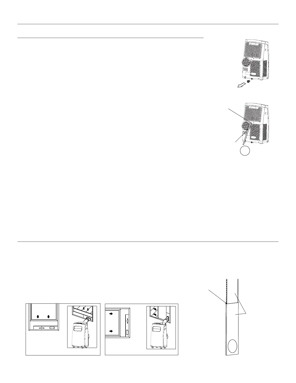
Carefully move the unit to a drain location, remove the bottom drain plug and
let the water drain away (see Figure E). Reinstall the bottom drain plug and
restart the machine until the P1 symbol disappears. If the error repeats, call for
service.
NOTE: Be sure to reinstall the bottom drain plug before using the unit.
DEHUMIDIFYING MODE ONLY: Remove the upper drain plug from the back of the unit and simply attach the
drain hose to the hole. Place the open end of the hose adapter directly over the drain area in your oor or into
another receptacle (see Figure F).
NOTE: Make sure the hose is secure so there are no leaks. Direct the hose toward the drain, making sure that
there are no kinks that will stop water ow. Place the end of the hose into the drain and make sure the end of
the hose is down to let the water ow smoothly (see Figure F). Do not li up the hose as this may cause water
to ow back into the unit.
WINDOW SLIDER KIT INSTALLATION
Your window slider kit has been designed to t most standard double-hung and slider windows, However, it
may be necessary for you to improvise/modify some aspects of the installation procedures for certain types of
windows. Please refer to Figure G & Figure H for minimum and maximum window openings. The window slider
kit can be xed with an included security peg (see Figure I).
Continuous
drain hose
Fig. F
Fig. E
√
Remove upper
drain plug
Window filler panel
Minimum: 2’ 1/8” (67.5cm)
Maximum: 4’ (123cm)
Fig. G
Standard
Double-hung
Window
Horizontal
Slider
Window
Fig. H
Window filler panel
Minimum: 2’ 1/8” (67.5cm)
Maximum: 4’ (123cm)
Fig. I
Window filler
panel
Security Peg