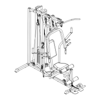
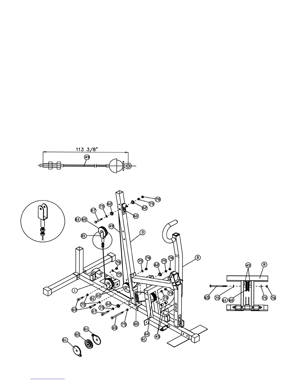
STEP 9 (See Diagram 9 & Cable Loop Diagram)
A.) Insert the 113” Cable (#49) through the upper hole on Front Vertical Frame (#3). Attach
a Pulley (#60) to the Cable. (NOTE: There is no Cable Cover needed.) Secure it with
one M10 x 2 9/16” Hex Bolt (#67), two ∅ 13/16” Flat Washers (#75), two Bushings
(#62), and one M10 Aircraft Nut (#78).
B.) Pull the Cable downwards to the open bracket on the Front Vertical Frame (#3) and
install another Pulley set.
C.) Draw the Cable through the hole at the bottom of the Front Vertical Frame (#3) to the
Front Press (#8). Attach another Pulley set to the Cable and secure it with one M10 x 5
11/16“ Hex Bolt (#65), two ∅ 13/16” Washers (#75), two Plastic Spacers (#45), and one
M10 Aircraft Nut (#78). NOTE: See Detail B to install the Plastic Spacer.
D.) Draw the Cable backward through the hole at the bottom of the Front Vertical Frame
(#3). Attach another Pulley and secure it with one M10 x 2 9/16” Hex Bolt (#67), two ∅
13/16” Flat Washers (#75), two Bushings (#62), and one M10 Aircraft Nut (#78).
E.) Draw the Cable back to the first bracket behind the Front Vertical Frame (#3). Install
another Pulley set.
F.) Pull the Cable upward towards the Single Floating Pulley Bracket (#21) previously
installed in Step 8F. Screw the Bolt into the Bracket.
12