Do you have a question about the Impex APEX WM-348.1 and is the answer not in the manual?
Ensure children and pets remain clear of the machine. Do not leave children unattended.
Machine is intended for use by one person at a time.
Stop exercise and consult a physician for abnormal symptoms like dizziness or chest pain.
Position on a clear, level surface, away from water or outdoors.
Keep hands clear of all moving machine parts during operation.
Wear suitable workout clothing and footwear; avoid loose items.
Use the machine strictly for its designated purpose as outlined in the manual.
Keep the area around the machine free from sharp objects.
Disabled individuals require qualified supervision for safe operation.
Always perform stretching exercises to warm up before each workout session.
Never operate the machine if it is not functioning properly.
A spotter is recommended during exercise for added safety.
Consult a physician before starting any new exercise program.
Use provided circles to check the correct size of washers, bolts, and screws.
Contact customer service for any defective or missing parts.
Connect rear upright beams with a cross brace using specified hardware.
Insert backrest adjustment bar for desired incline.
Insert bar catches for weight bar height adjustment.
Connect front stabilizer to main seat support and cross brace.
Attach diagonal support to main seat support and front stabilizer.
Securely tighten all previously installed nuts and bolts.
Insert lock pin into main seat support for backrest adjustment.
Attach butterfly using bolt, nut, and lock knob to rear upright beam.
Secure butterfly handle to butterfly using carriage bolt and nut.
Attach leg developer to front stabilizer using axle and screw.
Insert foam roll tubes and foam rolls onto the leg developer.
Place spring clips onto leg developer and butterfly posts.
Attach backrest supports to main seat support and backrest adjustment bar.
Secure backrest board to backrest supports with bolts and washers.
Place and secure seat onto the main seat support.
Insert arm curl stand into front stabilizer and secure with knob bolt.
Attach arm curl pad to arm curl stand with bolts and washers.
Attach cable to pulley and lat bar frame using bolt, bushings, washers, and nut.
Slide weight holder onto lat bar frame and connect cable with hook.
Connect lat bar to cable with a hook for lat pull down.
Remove arm curl and lat bar frame for vertical storage.
Pull lock pin on main seat support to fold bench vertically.
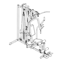
Visual representation of all machine parts with corresponding key numbers.
Detailed list of all parts, their key numbers, descriptions, and quantities.
Product warranty details, duration, and limitations for workmanship and material.
Procedure for product returns, including pre-authorization and freight responsibilities.
Instructions and required information for ordering replacement parts via phone or email.
| Brand | Impex |
|---|---|
| Model | APEX WM-348.1 |
| Category | Home Gym |
| Frame Material | Steel |
| Seat Material | Vinyl |
| Assembly Required | Yes |
| Number of Stations | 1 |
| Finish | Powder Coated |
| Adjustability | Adjustable Seat |
| Type | Multi-station home gym |
| Pulley System | Dual pulley system |