ASSEMBLY INSTRUCTION
STEP 1 (See Diagram 1)
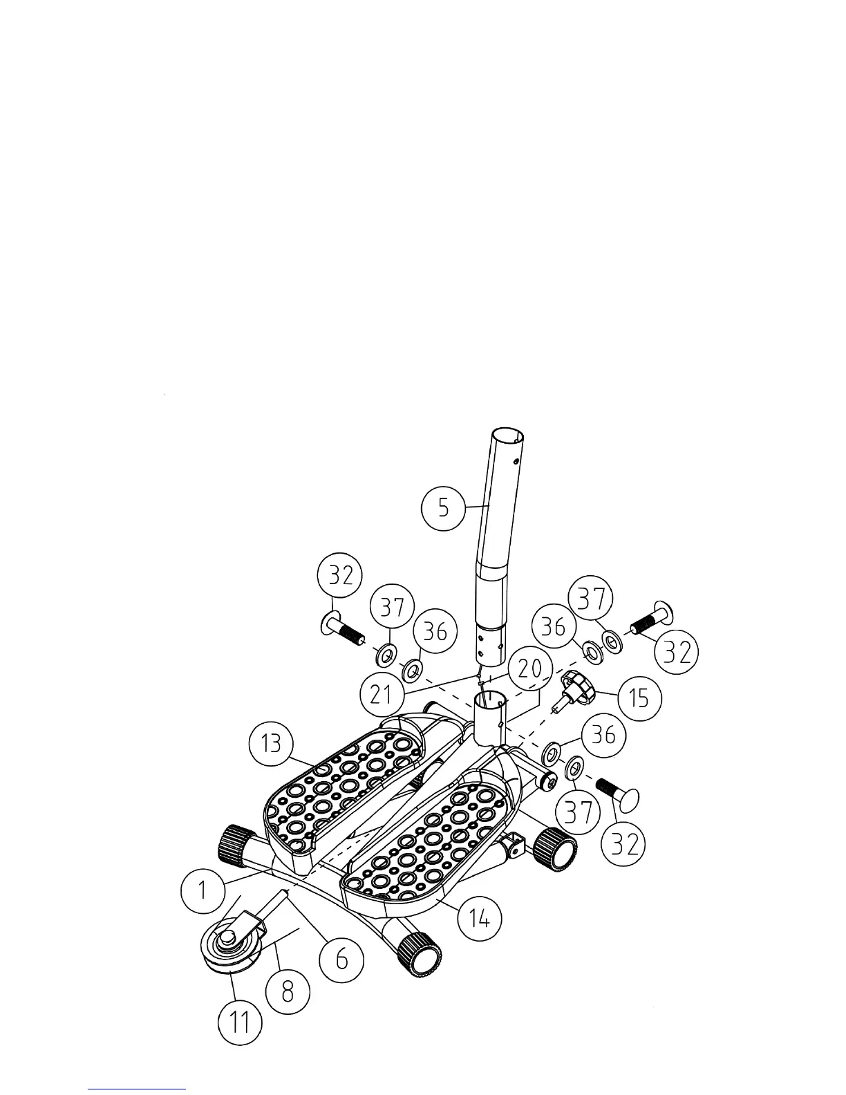
A.) Thread the Knob Bolt (#15) into the hole in the font of the Base Frame (#1). Turn the
Knob Bolt clockwise to secure the Pedals (#13). Note: The height of the pedals can be
adjusted by turning the Knob. Clockwise to increase the height and counterclockwise to
decrease the height.
B.) Connect the Magnet Sensor Wire (#20) from the Base Frame to the Computer Sensor
Wire (#21) from the Lower Frame (#5).
C.) Insert the Lower Frame into the Base Frame. Secure it with four M8 x 5/8” Allen Bolts
(#32), four Ø 5/8” Lock Washers (#37), and four Ø 5/8” Curved Washers (#36).
DIAGRAM 1
5