ASSEMBLY INSTRUCTION
Tools Required Assembling the Machine: Two Adjustable Wrenches and Allen
Wrenches. NOTE: It is strongly recommended two or more people assembling this
machine to avoid possible injury.
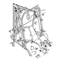
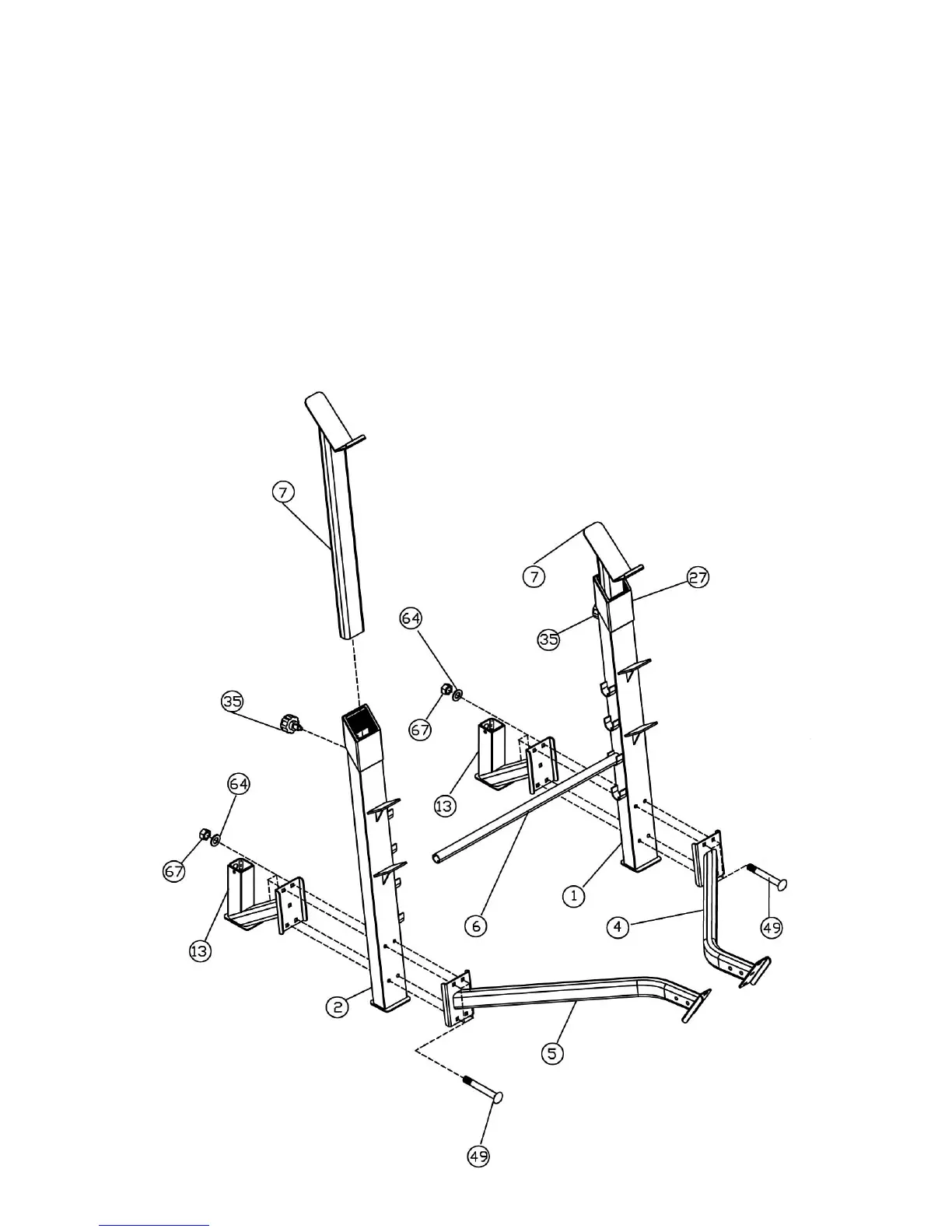
STEP 1 (See Diagram 1)
A.) Attach the Left Support Frame (#4) and the Rear Support (#13) to the Left Upright
Beam (#1). Align the holes. Secure them together with four M10 x 2 ¾” Carriage Bolts
(#49), Ø ¾” Washers (#64), and M10 Aircraft Nuts (#67). Do not tighten the Nuts and
Bolts yet. Repeat the same procedure to install the Right Support Frame (#5) and the
other Rear Support to the Right Upright Beam (#2).
B.) Insert two Crutches (#7) into the openings on the top of the Upright Beams. Secure
them with two M18 x Ø ½” Lock Knobs (#35).
C.) Place the Backrest Adjustment Bar (#6) on the selected slot on the Upright Beams to
obtain the desired backrest incline.
6