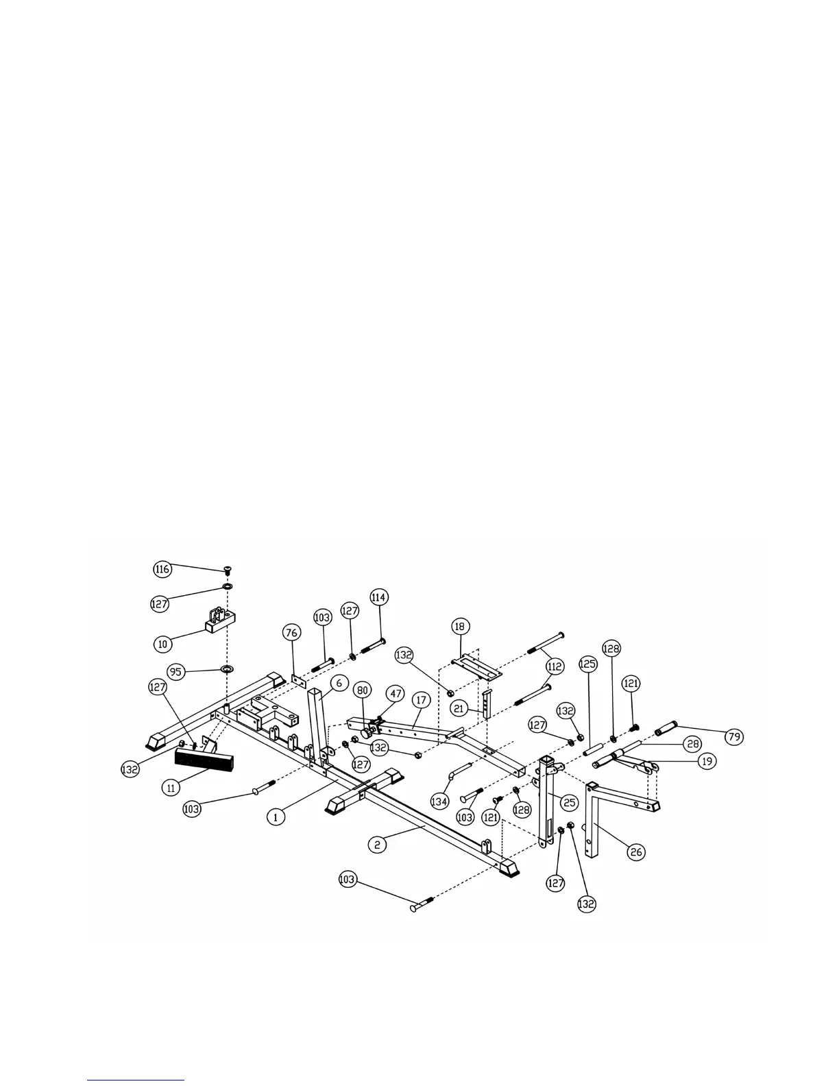
A.) Attach Foot Support (#11) to the Main Base Frame (#1). Secure it with one M10 x 2 ¾”
Carriage Bolt (#103), 4” x 2” Bracket (#76), ∅3/4” Washer (#127), and M10 Aircraft Nut (#132)
to the rear hole. Secure the front hole with one M10 x 2 ½” Allen Bolt (#114) and ∅3/4”
Washer (#127).
B.) Slide a ∅5/8” Ring (#95) onto the pivot axle on the back of the Main Base Frame (#1). Attach
the Swivel Frame (#10) onto the axle. Secure it with a ∅3/4” Washer (#127) and M10 x ¾”
Allen Bolt (#116).
C.) Attach the Leg Developer Holder (#25) to the Front Base Frame (#2). Secure it with a M10 x 2
¾” Carriage Bolt (#103), ∅3/4” Washer (#127), and M10 Aircraft Nut (#132).
D.) Slide the Sliding Block (#47) onto the Main Seat Support (#17). Secure it with a Quick Release
Pin (#80). Attach the back end of the Main Seat Support (#17) to the bracket on the bottom of
the Front Vertical Beam (#6). Secure it with a M10 x 2 ¾” Carriage Bolt (#103), ∅3/4” Washer
(#127), and M10 Aircraft Nut (#132). Secure the front end of the Main Seat Support (#17) to
the Leg Developer Holder (#25) with a M10 x 2 ¾” Carriage Bolt (#103), ∅3/4” Washer (#127),
and M10 Aircraft Nut (#132).
E.) Attach the Leg Developer (#26) to the Leg Developer Holder (#25). Insert a 2 3/16” Axle
through the pivot. Secure it with two M8 x 5/8” Allen Bolts (#121) and ∅5/8” Washers (#128).
F.) Attach the Arm Curl Handle (#19) to the front of the Leg Developer (#26). Insert a 12” Tube
(#28) through the Handle and push two Grips (#79) onto the Handle.
G.) Attach the Seat Bracket (#18) to the pivot tube on the Main Seat Support (#17). Secure it with
a M10 x 4 ¾” Allen Bolt (#112) and M10 Aircraft Nut (#132).
H.) Attach the Seat Incline Support (#21) to the bottom of the Seat Bracket (#18). Secure it with a
M10 x 4 ¾” Allen Bolt (#112) and M10 Aircraft Nut (#132). Adjust the incline with a L Shaped
Pin (#134).
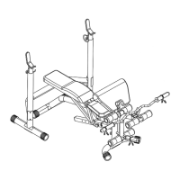
DIAGRAM 4
7
STEP 5 (See Diagram 5)