Do you have a question about the Impex MARCY MD-9010 and is the answer not in the manual?
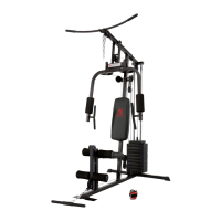
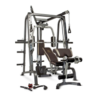
| Type | Home Gym |
|---|---|
| Material | Steel |
| Pulley System | Yes |
| Leg Developer | Yes |
| Press Arm | Yes |
| Lat Tower | Yes |
| Butterfly Arms | Yes |
| Weight Capacity | 300 lbs |
| Maximum Total Weight on Rack | 300 lbs |
| Maximum User Weight on Bench | 300 lbs |
General safety guidelines and warnings for operating the exercise machine.
Instructions for lubricating, cleaning, and maintaining the machine for optimal performance.
Connects the two base frames using a cross brace and specified bolts and washers.
Attaches front and rear vertical frames to the base and other structural components.
Attaches the rear vertical beam, weight glide base, and backrest board to the frame.
Connects the weight glide post, sliding weight post, and rear upper frame assembly.
Assembles the left and right upper frames, including pulley brackets and rear upper frame connections.
Attaches the butterfly base, pulley brackets, and butterfly arm pads to the main frame.
Attaches and routes the butterfly cable through pulleys for the right and left butterfly arms.
Installs various cables, pulleys, and brackets for the upper and middle sections of the machine.
Connects the sliding weight post cable through multiple pulleys and brackets.
Attaches the lower cable to pulleys, the pulley support frame, and connects the shiver bar.
Connects the main frame to the front and rear stabilizers and attaches the incline adjustment bar.
Attaches seat support frames and backrest supports, securing the incline mechanism.
Secures the backrest board and seat pad to the respective support frames using bolts and washers.
Attaches the leg developer to the main frame and installs foam rolls and Olympic sleeves.
Attaches the arm curl pad and handle to the arm curl stand and leg developer.
Information on how to order replacement parts, including contact details and required information.