ASSEMBLY INSTRUCTION
Tools Required to Assemble the Machine: Two Adjustable Wrenches and Allen Wrenches
NOTE: It is strongly recommended this machine be assembled by two or more people to
avoid possible injury.
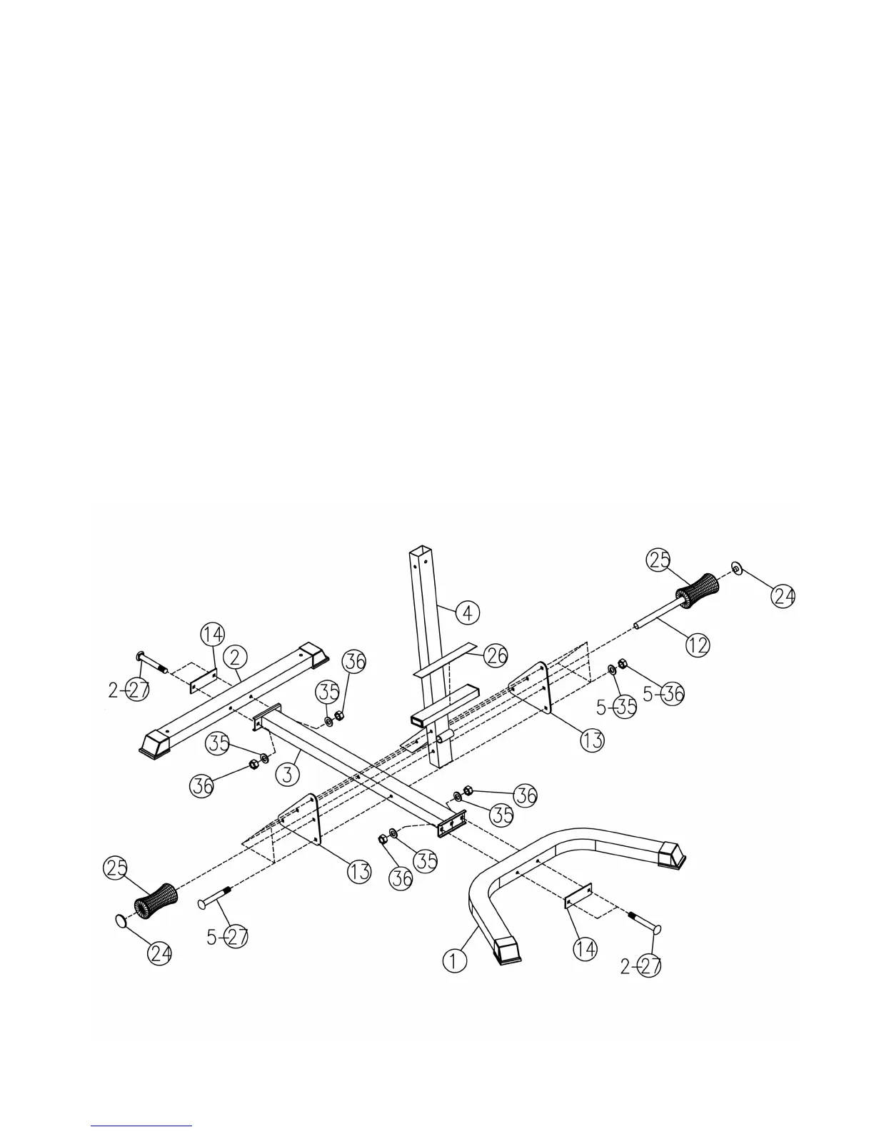
STEP 1 (See Diagram 1)
A.) Connect the Front Stabilizer (#1) to the Base Frame (#3). Secure it with two M10 x 3 ¾”
Carriage Bolts (#27), one Bracket (#14), two ∅ ¾” Washers (#35), and two M10 Aircraft Nuts
(#36). Repeat the same step to connect the Rear Stabilizer (#2) to the Base Frame (#3).
B.) Attach the Lower Vertical Frame (#4) to the Base Frame (#3). Secure it with two Triangle
Brackets (#13), one on each side of the Frame, five M10 x 3 ¾” Carriage Bolts (#27), ∅ ¾”
Washers (#35), and M10 Aircraft Nuts (#36).
C.) Insert the Foam Roll Tube (#12) halfway through the pivot on the Frame. Slide two Foam Rolls
(#25) onto the Foam Tube from both sides. Plug two Foam Caps (#24) to both ends.
D.) Attach the Non-slip Pad (#26) onto the top of the step on the Lower Vertical Frame.
DIAGRAM 1
4