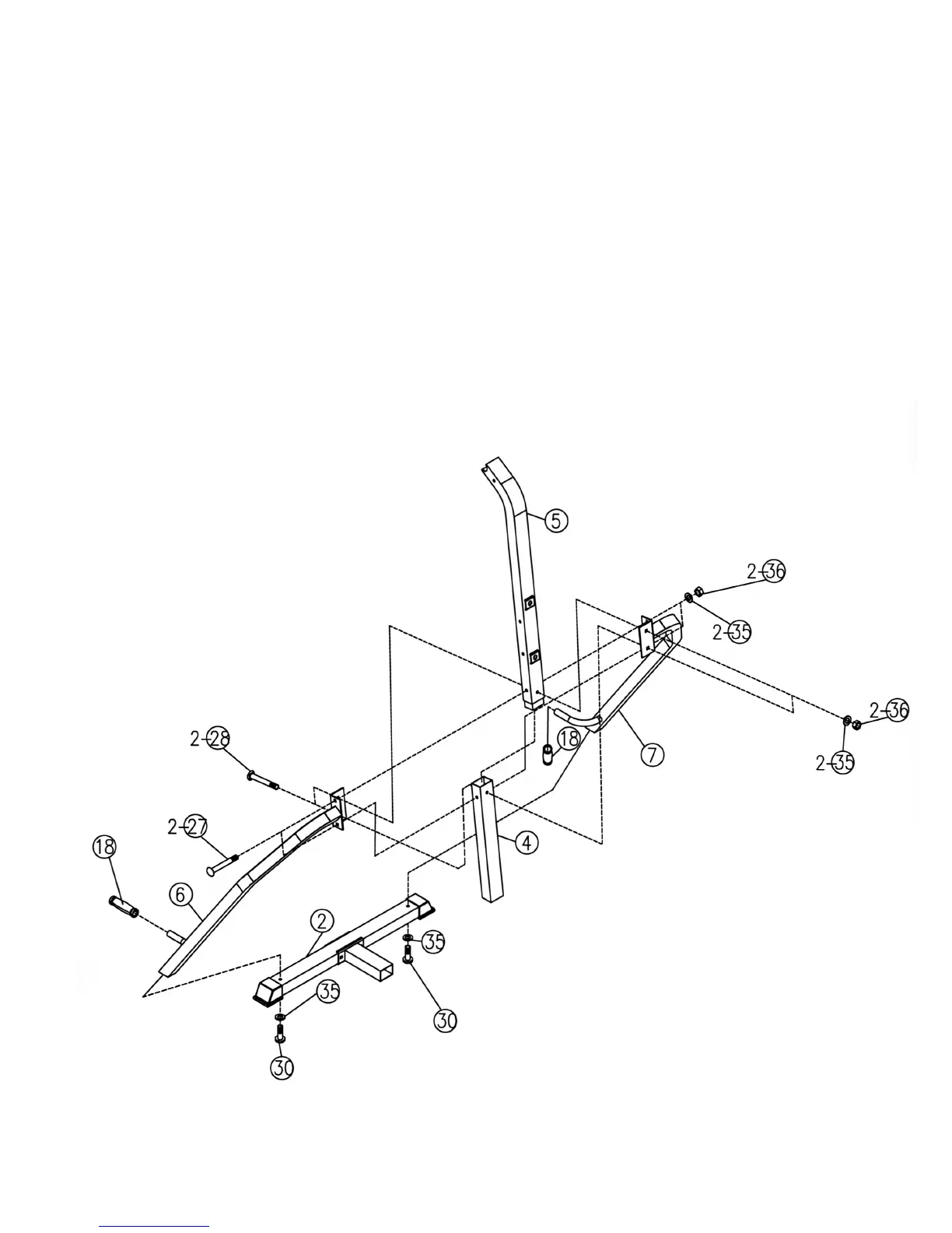
STEP 2 (See Diagram 2)
A.) Attach Left Support Frame (#6) onto the Rear Stabilizer (#2). Secure it with a M10 x 2 ½” Allen
Bolt (#30) and ∅ ¾” Washer (#35) from the bottom up. Repeat the same step to install the
Right Support Frame (#7) to the Rear Stabilizer.
B.) Insert the Upper Vertical Frame (#5) into the Lower Vertical Frame (#4). Attach top of the Left
& Right Support Frame (#6) & (#7) to both sides of the Frame. Align the holes and secure the
Support Frames to the Vertical Frame with two M10 x 3 ¾” Carriage Bolts (#27), ∅ ¾”
Washers (#35), and M10 Aircraft Nuts (#36). Secure the Vertical Frame with two M10 x 3”
Carriage Bolts (#28), ∅ ¾” Washers (#35), M10 Aircraft Nuts (#36).
C.) Slide two Short Grips (#18) onto the curl handles on the Support Frames.
DIAGRAM 2
5