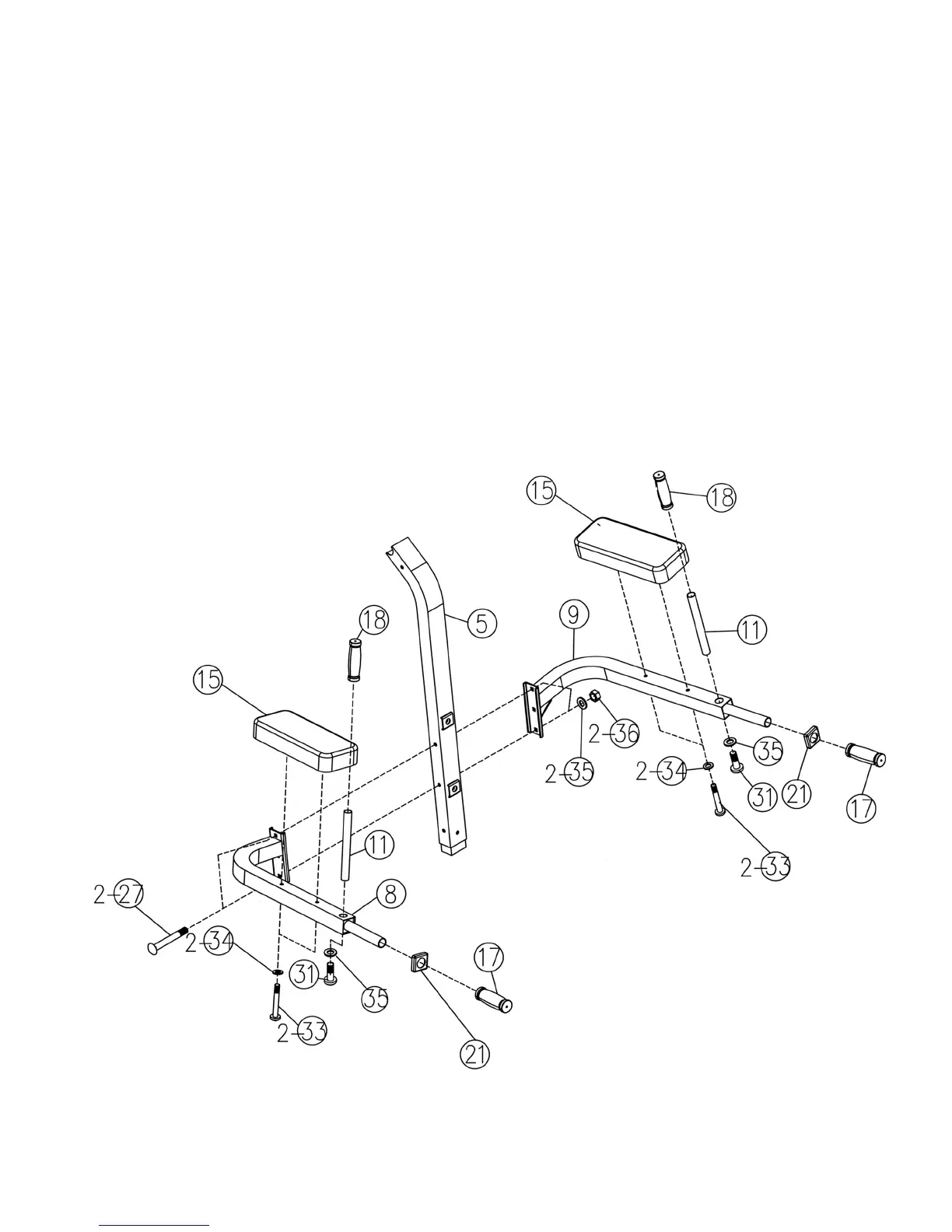
STEP 3 (See Diagram 3)
A.) Attach the Left Dip Support (#8) and Right Dip Support (#9) to the Upper Vertical Frame (#5).
Secure them with two M10 x 3 ¾” Carriage Bolts (#27), ∅ ¾” Washers (#35), and M10 Aircraft
Nuts (#36).
B.) Attach two Arm Pads (#15) to Left and Right Dip Supports. Secure each Pad with two M8 x 2
¼” Allen Bolts (#33) and ∅ 5/8” Washers (#34).
C.) Insert two Vertical Handles (#11) into the holes on the Dip Supports. Secure them with one
M10 x 5/8” Allen Bolt (#31) and ∅ ¾” Washer (#35) underneath each handle. Slide two ∅ 1”
Grips (#18) onto the Handles.
E.) Slide two Sleeves (#21) onto the Handles on the Dip Supports. Then slide two ∅ 1 3/8” Grips
(#17) onto the handles.
DIAGRAM 3
6