INSTALLATION INFORMATION
Accessories
CAUTION: DO NOT use the Metal-oxide Varistors (25 Vrms, 500 A, 77 V max
clamping) with mains power applications.
Plastic Cluster Housing (HMW700)
Each Impro (WRM) Wiegand Reader Module is supplied in a Customisable Black, ABS
Plastic housing, with the following features / items:
• Housing, consisting of a Base, a Cover and a selection of Cable Entry Gland
Plates.
• The Housing Base has:
− Two slots to hold the User-Selectable Cable Entry Plates
− Six knock-out Cable Entry Points
− Four Drill-out Cable Entry Points
• The Housing Cover and Base are held together with two Allen Head Screws
(M4 x 10 mm) through the cover of the housing.
• Five Ziploc bags, containing the following:
− Four Stand-Offs (for spacing the WRM away from the mounting surface)
and two Cluster Connector Covers (for closing off the cluster connectors
when not in use.)
− Two Metal-Oxide Varistors 25 Vrms, 500 A, 77 V max clamping.
− A 2mm Allen Key and a spare Hex Head Screw
− Two extra gland plates
− An extra Fixed Address Label, for installation site mapping
NOTE: The installer needs to obtain fasteners (< 5 mm Diameter to fit through the
supplied Stand-Offs) that are suitable for securing the Module to the
mounting surface – these are NOT supplied in the kit.
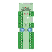
PCB Card for IPS Housing (HMW710)
Included in the packaging is:
• Impro Wiegand Reader PCB Card on a Base Plate.
• An extra Fixed Address Label, for installation site mapping
HMW300-0-0-GB-00 October 2013 Page 4
 Loading...