Remote Mounting
When it is advantageous to mount a WRM near to the relevant door (and some
distance from the Cluster Controller), the WRM may be connected to the Cluster
Controller using an S-Bus cable up to a maximum of 150 m (490 ft.) long. The
procedure is as follows:
• Check to see how many other Device Addresses are already connected to the
S-Bus Host “D” Terminal of the Cluster Controller. No more than eight Device
Addresses should be connected to an S-Bus.
• Obtain a suitable Isolated DC Power supply to power the WRM and any
readers and magnetic locks, etc., that may be connected to the WRM.
• Remove the Housing Cover from the WRM and hold the module base in
position, mark the mounting hole locations through the mounting holes in the
back of the Housing Base.
• Remove the WRM, drill the mounting holes.
• Use the Stand-Offs to provide space for cables behind the module, if
necessary – or to allow for an uneven mounting surface.
• Mount the WRM Housing Base firmly to the mounting surface, using fasteners
(not included) appropriate for the mounting surface material.
• Select the gland plates that best suit the installation and/or knock out the
cable entry points as needed.
• Connect the reader cables, the digital inputs and the relay terminals as
necessary for the installation
• Commission the WRM (and its readers) via the menu options on the Access
Control Application.
• Replace the WRM Housing Cover and fasten closed with the two Allen head
screws provided.
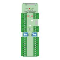
DIP-switch Settings
NOTE: Whenever the DIP-switch settings are modified reset the Impro WRM to
acknowledge the new settings by disconnecting and reconnecting the power
supply to the WRM.
Reader 1 Select and Reader 2 Select DIP-switch Settings
Each of the Reader Ports has a 4-way DIP-switch to select the function of that Port.
NOTE: Where you have no Advanced Wiegand Reader (Impro Multi-discipline
Reader) connected, setting both Remote DIP-switches to the all off position
during an Auto-ID will not return any Fixed Addresses.
NOTE: When Wiegand and Multi Discipline Readers are used on the same
SYSTEM, all DIP Switches should take on the Wiegand settings.
HMW300-0-0-GB-00 October 2013 Page 8
 Loading...