EasyManua.ls Logo

impro technologies HMW701-0-0-NN-XX - User Manual

impro technologies HMW701-0-0-NN-XX
20 pages
Print Icon
To Next Page IconTo Next Page
Loading...
MODEL NUMBER:
HMW700-0-0-NN-XX HMW701-0-0-NN-XX
Wiegand Reader
Module
Impro (WRM) Wiegand Reader Module
INSTALLATION MANUAL
SPECIFICATIONS
The WRM is a Cluster Expansion Module that works in conjunction with an Impro
(CCM) Cluster Controller Module; offering a Wiegand Reader Interface solution that is
adaptable and scalable, while also accommodating legacy hardware and software
suites.
Working Environment
Plastic Housing ............................
(HMW700)
Designed to work in an indoor (dry)
environment similar to IP20. The Module is
not sealed against water.
PCB Card for IPS / 19” Rack .......
(HMW701)
Designed to work in an indoor (dry)
environment similar to IP20. The Card is not
sealed against water.
Power
Input Voltage ................................
12 V DC to 15 V DC, polarity protected.
Power Requirements
Current (mA)
Power (W)
12 V DC with no Readers
connected and relays off ........
37
0.44
12 V DC with both relays
activated and maximum
reader load .............................
503
6
Question and Answer IconNeed help?

Do you have a question about the impro technologies HMW701-0-0-NN-XX and is the answer not in the manual?

impro technologies HMW701-0-0-NN-XX Specifications

General IconGeneral
Brandimpro technologies
ModelHMW701-0-0-NN-XX
CategoryControl Unit
LanguageEnglish

Summary

SPECIFICATIONS

Working Environment

Details the environmental conditions suitable for the WRM module, including IP rating and water resistance.

Power Requirements

Specifies input voltage range and power consumption under various load conditions.

Communication with Cluster Controller

Direct Communications

Describes direct communication interfaces and protocols between WRM and CCM.

S-Bus Device Port

Details the S-Bus interface for connecting devices to the WRM module.

Reader Options

Relay Outputs and Ratings

Information on the WRM's relay outputs, contact types, and contact ratings.

Digital Inputs

General Digital Input Configuration

Details type, resistance range, and protection for digital inputs.

LED Status and Diagnostic Indicators

Status and Data LED Indicators

Information on red Status LED and green Data LED functions for system monitoring.

Input and Relay Status LEDs

Details on LEDs for digital input status and relay activation.

INSTALLATION INFORMATION

Included Accessories

Lists accessories provided with the WRM, including housing parts and labels.

General Installation Guidelines

Module Clustering

Procedure and considerations for clustering WRM modules with the Cluster Controller for system expansion.

S-Bus Connectivity for Remote Use

Guidelines for connecting the WRM using the S-Bus for remote installations.

Reader Distance Specifications

Wiegand;Multi-Discipline Reader Distance

Maximum cable distances for Wiegand and Multi-discipline readers, and between reader units.

EARTH Connection

Arc Suppression

Mounting the WRM Module

Clustering Installation Procedure

Steps for mounting the WRM module and integrating it into a clustered system.

Remote Mounting Procedures

DIP-switch Settings

Reader 1 & 2 DIP-switch Configuration

Guide to setting DIP-switches for selecting reader functions and modes.

Wiegand Modes

Wiegand Mode Rules

ELECTRICAL CONNECTIONS

Key Component Positions Diagram

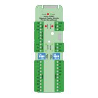
Diagram identifying key components and connection terminals on the WRM Printed Circuit Board.

Connecting Multi-Discipline Readers

Connecting to Wiegand Readers

Connecting to a Multi-mode Remote

Connecting Other Devices

S-Bus and Power Wiring for Remote Installation

Power-on Self-test

WRM Address Information

Fixed Address Label Usage

Guidance on attaching and using fixed address labels for site mapping and terminal identification.

GUARANTEE OR WARRANTY