Do you have a question about the Incon 1250B and is the answer not in the manual?
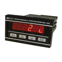
Details the panel-mount case dimensions and installation requirements for the 1250B unit.
Provides the physical dimensions and panel cutout specifications for the 1250B unit.
Illustrates typical wiring configurations for synchro transmitter connections and analog output.
Explains terminal functions, DIP switch settings, and communication connector pinouts for setup.
Details how to configure analog output settings using switches and trim-pots.
Visual representation of the menu structure and parameter selection process for programming the device.
Lists and describes all available menu options and their programmable ranges for configuration.
Lists commands for configuring and controlling the device via RS-232 or RS-485 serial interfaces.
Explains the functionality, wiring, and programming of the analog output signal for remote monitoring.
Describes how to configure and use high and low relay limits for alarm and feedback functions.
Details the seven available operating modes for the RS-232 serial communication port.
Explains the use of the RS-485 interface for MODBUS communication and device configuration.
Provides steps for calibrating the analog output signal using menu commands or serial port.
Covers self-diagnostic tests, power fail behavior, LED tests, and relay testing.
Lists and explains all displayable error codes, their meanings, and troubleshooting guidance.
Provides a comprehensive list of the device's electrical, physical, and performance specifications.
| Brand | Incon |
|---|---|
| Model | 1250B |
| Category | Measuring Instruments |
| Language | English |