28
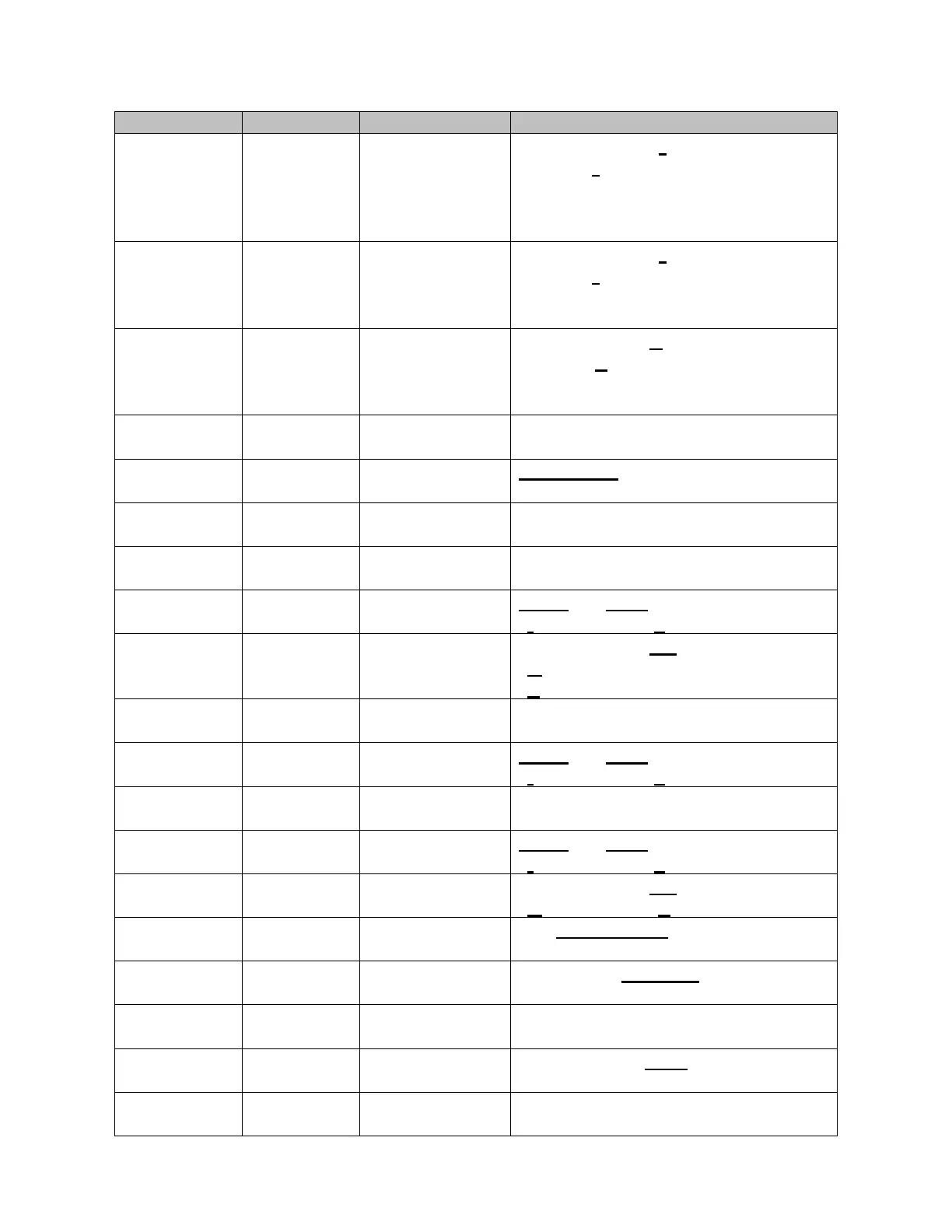
Table 3.8 RS-485 MODBUS Register Definitions
000000000000000s
LSB (s) selects mode
0 – run mode
1 – setup mode (must be 1 before any
program parameter can be changed)
synchro input
signal status
000000000000000s
LSB (s) indicates status
0 – OK Input signal is present
1 – ALARM Input signal is lost
select floating
point format
00000000000000ff
LSBs (ff) selects format
00 – bcd floating-point format
01 –IEEE floating-point format
floating point number (bcd or IEEE):
bcdabcdbbcdcbcdd bcde000000vspppp
tttttttttttttttt 16 bits, number of turns
bcdabcdbbcdcbcdd bcde000000vspppp
bcdabcdbbcdcbcdd bcde000000vspppp
tttttttt0000nnnn “0000” are unused bits
“t”= tap number “n”= neutral number
00000000000000HL bit = 1 to reset
“H”= high draghand
“L”= low draghand
peak draghand
scaled mode
bcdabcdbbcdcbcdd bcde000000vspppp
peak draghand
segmented mode
tttttttt0000nnnn “0000” are unused bits
“t”= tap number “n”= neutral number
valley draghand
scaled mode
bcdabcdbbcdcbcdd bcde000000vspppp
valley draghand
segmented mode
tttttttt0000nnnn “0000” are unused bits
“t”= tap number “n”= neutral number
00000000000000HL relay on, bit = 1
“H”= high relay “L”= low relay
00000000000mmmmm 5 LSBs
(see list of modes on page 14)
bcdabcdbbcdcbcdd bcde000000vspppp
set digits left of
the decimal point
bcdabcdbbcdcbcdd bcde000000vspppp