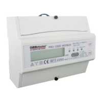
The PRO1250D CT M-bus MID is a DIN rail three-phase four-wire energy meter designed for accurate energy registration. It is a transformer-connected electronic meter suitable for indoor use and is compliant with international standards such as IEC 62052-11 (2003) and IEC 62053-21 (2003) for active energy meters (classes 1 and 2). The device also holds EC-Type examination certificate 6990-11 and CE certificates, confirming its adherence to European directives like 2004/22/EC.
Function Description
The PRO1250D CT M-bus MID measures active energy in three-phase four-wire systems. It generates pulses proportional to the measured energy, which can be read via a pulse output. Additionally, it features an M-bus communication port for remote data reading and configuration. The meter is designed for energy registration in one direction only, meaning it is not suitable for reverse energy measurement.
Important Technical Specifications
Meter Type: PRO1250D CT M-bus MID
Nominal Voltage (Un): 230/400V AC (3~)
Operational Voltage: 161/279V ~ 300/520V
Frequency Range: 50 or 60 Hz ±10%
Basic Current (Ib): 1.5A
Maximum Rated Current (Imax): 6A
Operational Current Range: 0.4% Ib - Imax
Peak Current Withstand: 30Imax for 0.01s
Insulation Capabilities:
- AC voltage withstand: 4kV for 1 minute
- Impulse voltage withstand: 6kV – 1.2μS waveform
Accuracy Class: 1/B
Internal Power Consumption: ≤2W / 10VA per phase
Test Output Flash Rate (PULSE LED): 1600 imp/kWh
Pulse Output Rate: 1600 imp/kWh
Data Save: More than 10 years without power
Operating Humidity: ≤ 75%
Storage Humidity: ≤ 95%
Operating Temperature: -25°C - +55°C
Storage Temperature: -25°C - +55°C
Protection Against Penetration of Dust and Water: IP51
Insulating Encased Meter Protective Class: II
Dimensions:
- Height with protection cover: 130 mm
- Height without protection cover: 100 mm
- Width: 126 mm
- Depth: 65/59.5 mm
- Size of connection clamps: 10 x 8 mm
- Weight: 0.7 kg (net)
Materials:
- Front panel: PC flame resistant plastic
- Cover: ABS flame resistant plastic
- Case: ABS flame resistant plastic
M-bus Communication Specifications:
- Bus Type: M-bus
- Baud Rate: 300, 2400 (default), 9600
- Range: ≤380m (250PCS), ≤3600m (64PCS)
- Cable: JYSTY (n×2×0.8)
- Protocol: EN13757-3
- Max. Number of Meters: 64 (dependent on converter, baudrate, and installation circumstances)
Usage Features
Installation: The meter is designed for installation on a 35mm DIN rail. It should be placed in a well-ventilated, dry, and easily readable location. For areas with frequent surges (e.g., thunderstorms, welding machines), a Surge Protection Device is recommended. The device must be installed by qualified personnel familiar with applicable codes and regulations, using insulated tools. An external switch or circuit-breaker, along with an overcurrent protection device (fuse or thermal cut-off), should be installed on the supply wires near the meter. The meter can be installed indoors or in a sufficiently protected outdoor meter box. To prevent tampering, an enclosure with a lock is recommended. All clamps should be properly tightened, and wires must fit correctly to avoid bad contact and sparking. Protection covers must be replaced after installation.
Operation:
- Working Indication: Three power indication LEDs on the front panel display the status of each phase: yellow for L1, green for L2, and red for L3. All three LEDs will illuminate under normal working conditions.
- Consumption Indication: A red LED (1600 imp/kWh) on the right side of the display flashes to indicate energy consumption. A faster flash rate signifies higher power consumption.
- Reading the Meter: The meter features a 7-digit LCD display. The decimal count varies (6+1 or 7+0) depending on the CT ratio setup. For CT ratios of 200/5 and above, a 7+0 screen is shown. The register cannot be reset due to MID regulations.
- Pulse Output: An isolated pulse output generates pulses proportional to measured energy. It is a polarity-dependent, open collector transistor output requiring an external voltage source (Ui) of 5-27V DC with a maximum input current (Imax) of 27mA DC. Connect 5-27V DC to connector 9 (collector) and the signal wire (S) to connector 8 (emitter).
- M-bus Communication: The meter is equipped with an M-bus port for data reading, conforming to the EN13757-3 standard. To read data, PC software and an M-bus level converter are required, connecting to terminals 10 and 11. The default communication address is 1.
CT Ratio Settings: The default CT ratio is 5:5. It can be changed once to one of 27 available options (e.g., 50/5, 100/5, 3000/5) within the first 30 seconds after power-on. After this period or once set, the CT ratio is locked and can only be reset by the manufacturer, adhering to MID regulations. Changing the CT ratio will divide the pulse output rate accordingly (e.g., 1600/50 = 32 pulses per kWh for a 250/5 ratio).
Maintenance Features
General Maintenance: Maintenance and repair should only be performed by qualified personnel using insulated tools. The meter case is sealed, and breaking any seals voids the warranty and may affect functionality or accuracy. The device should not be dropped or subjected to physical impact, as it contains high-precision components.
Troubleshooting:
- No Register Count: Check if a load is connected and if the consumption LED is flashing. If not, contact technical support for a meter replacement.
- Wrong Pulse Output Rate: Verify the CT ratio setting (refer to section 14). If incorrect, contact technical support.
- No Pulse Output: Ensure the external voltage source (5-27V DC) is correctly supplied and connected to the pulse output terminals (pin 9+ collector, pin 8- emitter). If issues persist, contact technical support.
- No Data Received by M-bus Port:
- Check if the Meter ID (default 1) is correct.
- Reduce the distance between the meter and the reading device (max 1000m, max 64 PCS).
- Ensure M-bus wires are correctly connected to terminals 10 and 11.
- Keep the PRG button pressed while sending the command to change the meter ID.
- If problems persist, contact technical support.
- Power Supply Indicators (L1, L2, L3 LED) Off:
- Verify the meter is connected to a power source.
- Check if L1, L2, L3, and N are correctly connected and screws are tightened.
- Measure AC voltage between N and L connections (should be 230V AC) and between L connections (should be 400V AC).
- Check for defective fuses or surge protection. If issues persist, contact technical support.
- Red Consumption LED Not Flashing: Connect a load to the meter. Check the load on the line with an Ohm-meter if the load value is very low. If issues persist, contact technical support.
- Infrared Communication Not Working:
- Check if the meter ID (default 0) is correct.
- Ensure the distance between the transmitter and receiver is no more than 5 meters and the receiver is in direct sight of the infrared interface.
- Set the baudrate to the default 1200 bps.
- Contact technical support for the meter communication protocol.