Contact Infiltrator Water Technologies 1-800-221-4436 for additional technical and product information.
3
AQUAWORX IPC PANEL INSTALLATION INSTRUCTIONS
II. Installing the IPC Panel
NOTE: A qualified electrician must perform all wiring.
Complete wiring diagram available at www.aquaworx.com
The following components and tools may be required
for installation:
• Screwdriver (sm and med size flat head)
• Pipe cutter and tape measure
• Fish tape
• Wire strippers/cutters
• Electrical tester
• Drill
• 3⁄4” to 1” screws
• 1” PVC coupler
• Step bit
• Hole saw
• Electrical conduit
• Electrical tape
• Splice box for pump connection
• Waterproof wire connectors
• 1” PVC (for transducer handle, amount determined by
tank depth (6’ length typical)
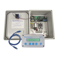
FIGURE 2: IPC PANEL WIRING SETUP AND
TRANSDUCER 3-WIRE CONNECTION
1. Mount the IPC Panel to the wall or post. Position the
IPC Panel so that the power supply enters the IPC Panel
through the bottom approximately 1” to the right of the
audible alarm unit.
2. On Simplex Panels drill two holes (3 holes for duplex)
in the bottom of the enclosure spaced approximately 2”
apart and in line with the audible alarm unit. When facing
the panel, the order of conduit connections from left to
right is shown below, as well as illustrated in Figure 2:
Power in: 2 dedicated 20 amp circuits from house to
power the panel, 120V (1) and pump, 120V or 220V(2)
Power out: Power supply from panel to pump
Transducer signal wire: Signal transmission from panel
to pump
NEMA 4X fittings must be installed in each field-drilled hole
to retain the integrity of the enclosure’s 4X rating.
Dedicated pump circuit from supply (#2)
(120 or 220 volt, 20 amp source; up to a 2 HP pump)
Power from panel to pump
(pump A for duplex)
Transducer signal wire terminal strip
Varistor surge suppressor
Ground terminals
Transducer wire and power in/out conduit connections
Audible alarm unit
Circuit board
Dedicated alarm from supply (#1)
(120 volt, 20 amp source)
 Loading...