Contact Infiltrator Water Technologies 1-800-221-4436 for additional technical and product information.
4
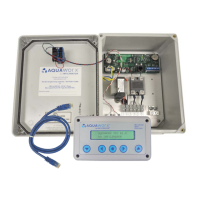
AQUAWORX IPC PANEL INSTALLATION INSTRUCTIONS
3. Power to pumps: run the panel (s) power wires from
the IPC Panel to the septic tank riser. Connect the wiring
in the splice box using water-tight connectors. Connect
pump wires to the IPC Panel by carefully following the
wiring diagram enclosed with the panel. A gas-tight seal
(see Figure 1) is required to prevent corrosive septic gases
from migrating into the IPC Panel.
4. Power to controller: wire the supply circuit to the panel.
Aquaworx recommends that the panel be wired to two
designated circuits. An external disconnect should be
incorporated into the supply circuit and mounted within
easy reach of the IPC Panel. Note: Site specific codes
have final authority on external wiring requirements.
III. Installing the Pressure Transducer
and Bell Assembly
The pressure transducer bell assembly replaces the tradi-
tional float tree assembly. The 1” PVC stand pipe may be
mounted by applying the same methods used to install a
float tree assembly.
1. Determine the position of the pressure transducer bell
assembly. The pressure transducer bell assembly must be
mounted so that it allows the liquid level to pump below
the bottom of the pressure transducer bell. This allows the
pressure transducer bell to get a fresh air bubble.
2. Feed the transducer signal wire and snorkel tube
through the 1” PVC stand pipe and glue to the pressure
transducer bell using a 1“ tee. The length of the stand
pipe when secured should position the bottom of the
pressure transducer bell above the top of the pump.
3. Cut off the snorkel tube approximately 9” lower
than the top of the stand pipe and secure it to the
transducer signal wire. The snorkel tube should be
positioned in the form of an upside-down U as high as
possible in the riser. This allows the snorkel tube to
create an air lock in the event of a flooded tank.
4) NOTE: The Z-bias value labeled on the side of the
pressure transducer bell. Later in the set-up, you will be
instructed to program the Z-bias into the IPC Panel.
5. Run the transducer signal wire back to the IPC Panel
and connect to the transducer signal wire terminal strip.
Connect Red to RD, blue to BL and black to BK (first
three positions). Make sure to leave enough cable in the
riser to allow for removal of the pressure transducer bell
assembly during maintenance. The transducer signal wire
is rated for direct burial. However, it can be run in a con-
duit. Site specific codes have final authority on installation
requirements.
NOTE: Do not attach the pressure transducer bell assembly to
the pump discharge pipe. Do not pinch or crimp the snorkel tube
tubing.
FIGURE 3: TRANSDUCER
Pump Power
Supply
Pump
Bell 4”
Above Off/
Idle Level
Pressure
Transducer
Bell
1” Tee
for Stand
Pipe
Drainage
1” PVC
Stand Pipe
Tank
Bracket
Snorkel Tube
Transducer
Signal Wire
Riser
Wall
Pump
Discharge
Excess
Transducer
Cable
 Loading...