6ED family - 2nd generation
Technical Description
Application Note 11 Rev. 1.3, 2014-03-23
AN-EICEDRIVER-6EDL04-1
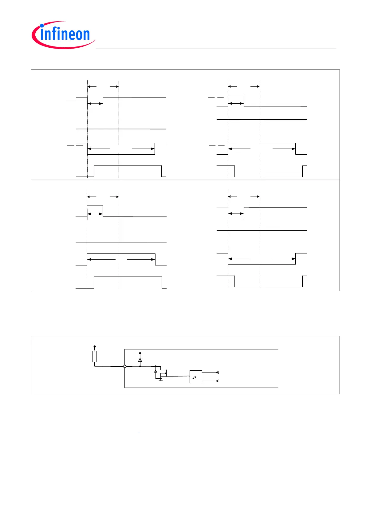
Figure 4 Short pulse suppression (left: short ON pulse; right: short OFF pulse)
a) and b): negative logic
c) and d): positive logic
3.3 Control output section (/FAULT)
Figure 5 Schematic of the structure of the /FAULT-pin
This pin indicates the failure status of the IC. The level of this pin is LOW in case of undervoltage lockout or
triggering of the overcurrent protection. An external pull-up resistor to VDD in the range of a few kΩ (e.g. 4.7 k)
is necesary for this open drain pin. The voltage at this pin is internally clamped to VCC, as one can see in the
internal structure according to Figure 5,. The internal pull-down FET has a typical resistance of R
ON,FLT
= 61 .
The delay time from the triggering event to the change of status at the /FAULT-pin is t
FLT
= 450 ns typically
according to the timing diagram shown in Figure 6.
FAULT
>1
from uv-detection
V
CC
R
ON,FLT
V
DD
from ITRIP-Latch
6ED family – 2nd generation
HIN/LIN
HIN/LIN
HO/LO
HO/LO
low
t
FILIN
t
IN
< t
FILIN
t
IN
t
IN
> t
FILIN
t
IN
HIN/LIN
HIN/LIN
HO/LO
HO/LO
high
t
FILIN
t
IN
< t
FILIN
t
IN
t
IN
> t
FILIN
t
IN
HIN/LIN
HIN/LIN
HO/LO
HO/LO
low
t
FILIN
t
IN
< t
FILIN
t
IN
t
IN
t
IN
> t
FILIN
HIN/LIN
HIN/LIN
HO/LO
HO/LO
high
t
FILIN
t
IN
< t
FILIN
t
IN
t
IN
> t
FILIN
t
IN
 Loading...