2
•
If the amplifier’s fuse must be replaced, use
only the same type and rating as that of the
original. Do not substitute another kind.
The Reference amplifiers are capable of
delivering high power levels, and require a
reliable connection to the vehicle’s electrical
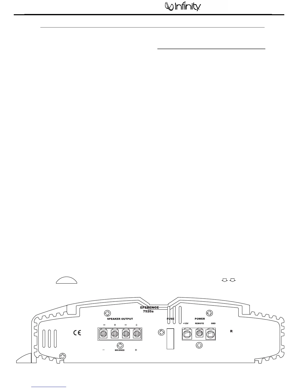
system in order to perform optimally. See
Figure 1 for connection location. Please
adhere to the following instructions carefully.
GROUND CONNECTION
Connect the amplifier’s Ground (GND) terminal
to a solid point on the vehicle’s metal chassis,
as close to the amplifier as possible. Refer to the
chart below to determine minimum wire-gauge
size. Sand away any paint from this location; use
a star-type-lock washer to secure the connection.
POWER CONNECTION
Connect a wire (see chart at right for appropriate
gauge) directly to the vehicle’s positive battery
terminal, and install an appropriate fuse holder
within 18" of the battery terminal. Do not
install the fuse at this time. Route the wire to
the amplifier’s location, and connect it to the
amplifier’s positive (+12V) terminal. Be sure to
use appropriate grommets whenever routing
wires through the firewall or other sheet metal.
Failure to adequately protect the positive wire
from potential damage may result in a vehicle
fire. When you are done routing and connecting
this wire to the battery and to the amplifier,
you may install the fuse at the battery. The
fuse value should be selected based on total
amplifier-current draw; see chart at right.
REMOTE CONNECTION
Connect the amplifier’s Remote (REMOTE)
terminal to the source unit’s Remote Turn-On
lead using a minimum of 18-gauge wire. If your
source unit does not have a remote turn-on
connection, connect the amplifier’s (REMOTE)
terminal to the vehicle’s accessory circuit.
SPEAKER CONNECTIONS
Refer to the application guides on the pages
that follow. Speaker connections should be
made using a minimum of 16-gauge wire.
NOTE: When using the low-level or high-level
inputs, the AUX outputs can be used to pass a
full-range line-level signal to another amplifier.
POWER CONNECTIONS