890 HD BF INSTALLATION INSTRUCTIONS
Gas supply routing.
Remove the three 4m screws from along the rear edge of the burner assembly. Carefully lift the burner up
from the right hand side to clear the injector tip and remove completely from the main body.
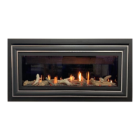
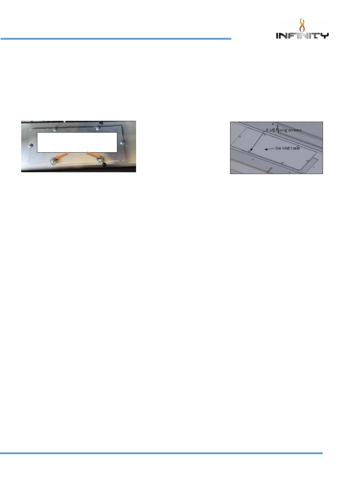
The Gas Connection can be made by removing the lower inspection cover located on the base of the firebox
sump. Remove the fixing screws(front 2 fixing will have spacers on this will help to keep the burner level when
installing the burner) and remove the plate plus gasket. Please note special attention should be taken not to
damage the gasket.
You will then have access to the isolating cock which is fitted in the supply feed.
A concealed gas fitting from the rear is required. It will be necessary to route the pipe to the rear of the unit,
taking into account the requirements of BS 6891 1988 dealing with enclosed pipes.
When installing the firebox into a cavity wall, any part of the installation pipe work installed in the void open
to the cavity wall must be enclosed in a gas tight sleeve. It must be sealed at the point at which the sleeved
installation pipe enters the fire (The Gas Safety (Installation and Use) Regulations Certificate of exemption
number 1 of 1996). Where the pipe enters the fire the outer sleeve must be sealed to the grommet and the
pipe must be sealed to its outer sleeve using suitable mastic.
Power lead routing.
The power supply for this appliance is provided via AC power adaptor 230 VAC. The main cable terminates
the rear center of the firebox. The length of the cable provided with the appliance is 1.65 metres. Care must
be taken when siting the firebox not to trap the exposed main cable within the builders opening.
Note: the power cable link to the transformer must be accessible for repairing handset and use with the
battery holder
The cable can be routed using the following two methods,
Method 1
Passing the cable through the side of the chimney breast. It is good practice to run the cable within a
sleeve of at least 15mm internal diameter, sealing the sleeve using a suitable sealant at the point the sleeve
/ cable terminates the chimney masonry.
Method 2
Remove a channel out of the outer skin of the Dry / wet plaster of the chimney breast up to the main power
point. Again it is good practice to run the cable within a sleeve of at least 15mm internal diameter.
With power points that exceed the 1.65 metre distance, an optional 2.0 metre extension cable is available
Part No 7147.
The cable system consists of retro fitting plug sockets which offers the following options. (Please see figure 5).