+6V 15
16
17
V+
1+6V
2
V+
3
18
4
O/P
19
5
O/P
20
6
V- V-
21
7
22
8
SD 24
+15V 23 9 +15V
10 SD
FR 25 11 FR
I/P 26 12 I/P
GND 27 13 GND
-15V 28 14 -15V
00228
NOTE: THE FOLLOWING PROCEDURES MUST BE FOLLOWED WHEN
INSTALLING NEW AMP MODULES:
FAILURE TO FOLLOW ONE OR MORE OF THESE STEPS MAY
RESULT IN THE INSTANT DESTRUCTION OF THE MODULE WHEN
POWERED UP.
1) Align white indent marker on Amp Module with indent marker on main
PCB; alternately position of label on the top of the module; incorrectly
replacing the Module 180
0
in the PCB slot will result in its destruction.
2) All AC powered test instruments (meters, oscilloscopes, etc.) must
have a floating ground, i.e. be connected to an isolation transformer.
3) Align and position the Amp Module before soldering.
4) Attach the amp Module with the mounting screws before soldering
or
powering up.
5) Use only rosin-core or non-acid core solder; thoroughly de-flux the
surfaces after soldering.
If the new Amp Module has larger mounting hole(s) in the case, and
the stock screws no longer will fit, and screws of the proper type can-
not be obtained locally order:
(2) part# 60301S (screws)
(2) part# 60301N (nuts)
BU-80 and HTS-10 rev “A, B” ONLY
4
IN
3
G
N
D
2
-15V
5
S/D
6
+15V
7
V
-
8
V
-
9
V
-
10
O
/
P
11
V
+
12
V
+
14
6V
13
V
+
1
FB
15
LIM
IT
PWR MODULE
CN101
00370
BU-80E & HTS-10 rev “C” ONLY
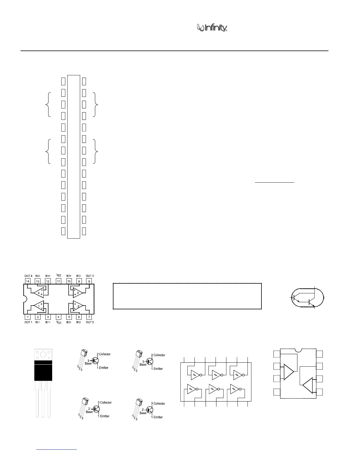
QUAD OP AMP,
LM324, TL074
U1, IC101
MOSFET TRANS
IRF530
Q2, 3
1. DRAIN
2. GATE
3. SOURCE
12
3
TRANS, NPN, KSP113
2SC1815
Q102, 103
TRANS, PNP, 2SA1015
Q101, 104, 105
TRANS, NPN, 2N5551
2N3904
Q1, 3
TRANS, PNP, 2N3906
MPS A56
Q2, 4, 5
JFET DUAL OPAMP
LF353N U1
V
CC
OUT2
IN2 (–)
IN2 (+)
OUT1
IN1 (–)
IN1 (+)
V
EE
1
2
3
4
8
7
6
5
3 COLLECTOR
2
BASE
1 EMITTER
TRANS, NPN
MPS A13 (Darl)
Q1
GNDA3Y2A2 Y3Y1A1
A4
21
3
4
5
A6
13
CC
V
14
A5
11
Y6
12
Y6
10
6
7
Y4
98
IC 74HC14N HEX SCHMITT
TRIGGER INVERTER
U2, 3
S53AM/S64AMI - Power Amp module SAFETY PART
Amplifier/Subwoofer
BU-80/BU-80EHTS-10
24
BU-80/HTS-10 INTEGRATED CIRCUIT/TRANSISTORS DIAGRAM