EasyManua.ls Logo

Infinity BU-150 User Manual

Infinity BU-150
23 pages
To Next Page IconTo Next Page
Page #1 background imageLoading...
Page #1 background image
Infinity Systems Inc.
250 Crossways Park Drive
Woodbury, N.Y. 11797
1-800-553-3332
A Harman International Company
Rev A 3/2000
BU-150
Powered Subwoofer
SERVICE MANUAL
Question and Answer IconNeed help?

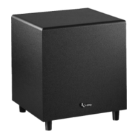
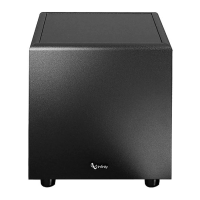
Do you have a question about the Infinity BU-150 and is the answer not in the manual?

Infinity BU-150 Specifications

General IconGeneral
BrandInfinity
ModelBU-150
CategorySubwoofer
LanguageEnglish

Summary

SAFETY INFORMATION

Warning

Any service must be performed by qualified personnel due to hazardous voltages.

Caution

Unit has hazardous voltages when plugged in; check voltage correspondence.

Leakage/Resistance Check

Perform leakage and resistance tests before returning the unit.

CONTROLS AND THEIR FUNCTION

BU-150 CONNECTIONS

Low-Level Signal Connection

Connects subwoofer using a low-level signal from preamp outputs via RCA.

Connecting Subwoofers

Low-Level Wiring (Figure 3)

Details low-level connections for single/stereo or mono subwoofer outputs.

High-Level Wiring (Figure 4)

Explains connecting via high-level inputs using speaker wire.

Connecting Subwoofers to Satellites

Satellite Connection Methods

OPERATION

Setting the Controls

Guides initial setup of Volume, Crossover, and Phase controls.

Crossover Frequency and Phase

Detailed explanation of setting the crossover frequency and phase.

Room Placement Advice

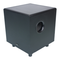
Advice on optimal subwoofer placement for best low-frequency enhancement.

TEST PROCEDURES

General Function Test

Steps for testing basic functionality using signal generator.

Driver Function Test

Steps to test the driver's DC resistance and listen for noises.

POWER AMP MODULE DIAGNOSTICS

Testing Flowchart

Step-by-step diagnostic procedure for the power amp module.

ELECTRICAL PARTS LIST

INTEGRATED CIRCUIT DIAGRAMS

Power Amp Module Installation

Critical procedures for installing the power amp module to avoid destruction.

SCHEMATIC DIAGRAM (Part 1)

BU-150 Schematic 1 of 2

Shows the first part of the electronic schematic for the BU-150.

SCHEMATIC DIAGRAM (Part 2)

BU-150 Schematic 2 of 2

Shows the second part of the electronic schematic for the BU-150.

Related product manuals