12
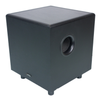
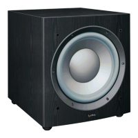
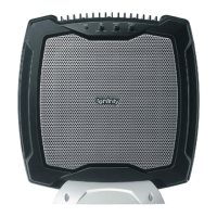
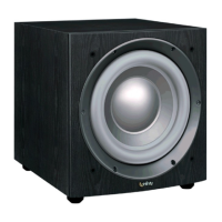
Amplifier/Subwoofer BU-150
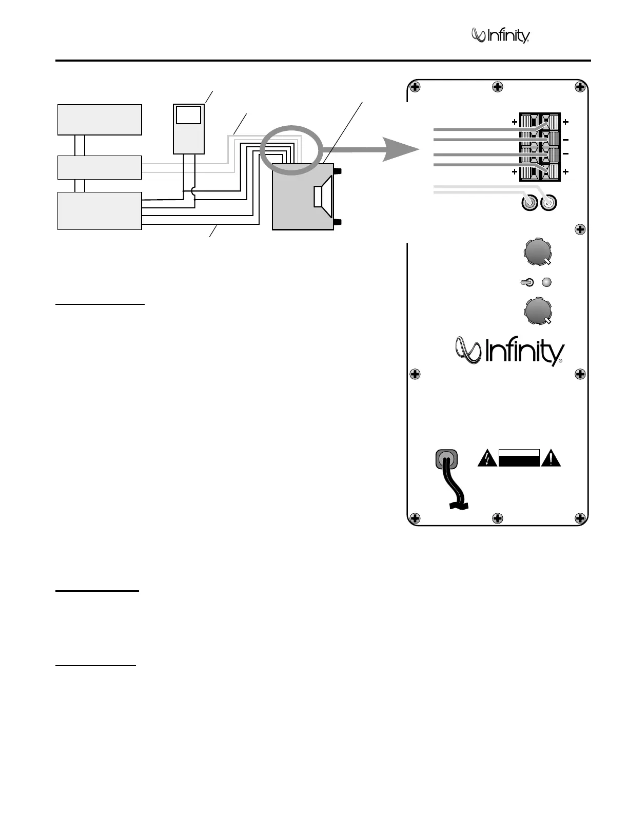
BU-150 TEST SET UP AND PROCEDURE
TO REDUCE THE RISK OF ELECTRIC SHOCK. DO NOT
EXPOSE THIS EQUIPMENT TO RAIN OR MOISTURE
CAUTION
RISK OF ELECTRIC SHOCK
DO NOT OPEN
120V
60Hz
250W
BU-150
Digital
Technology
Powered Subwoofer
180
o
0
o
Min
50
Max
150
Level
Low
Pass
R
RR
L
LL
Power
Phase
SPKR
IN
SPKR
OUT
Line Input
OUTPUT
FROM
AMPLIFIER
FROM PRE AMP
AMPLIFIER
CD PLAYER
PRE AMP
AC VOLT METER ( 6V )
BU-150
UNDER TEST
LINE LEVEL
SPEAKER LEVEL
General Function
UUT = Unit Under Test
1. Connect both right and left line level inputs (RCA) to signal
generator and UUT. Use Y-cable if necessary from
mono source. VOLUME control should be full counterclockwise.
2. Turn on generator, adjust to 50mV, 50 Hz.
3. Plug in UUT; red LED should be ON. Turn VOLUME control
full clockwise. Low Pass control should be set fully clockwise (150)
4. LED should turn Green; immediate bass response should be
heard and felt from port tube opening.
5. Turn off generator, turn VOLUME control fully counterclockwise,
disconnect RCA cables.
6. Connect one pair of speaker cables to either high level input
terminal on UUT. Cables should be connected to
an integrated amplifier fed by the signal generator.
7. Turn on generator and adjust so that speaker level output is
2.0V, 50 Hz. Turn VOLUME control full clockwise.
8. Green LED should light, immediate bass response should be
heard and felt from the port tube opening.
Sweep Function
1. Follow steps 1-4 above, using a sweep generator as a signal source.
2. Sweep generator from 20Hz to 300Hz. Listen to the cabinet and drivers for any rattles, clicks, buzzes or any
other noises. If any unusual noises are heard, remove driver and test.
Driver Function
1. Remove driver from cabinet; detach + and - wire clips.
2. Check DC resistance of driver; it should be 6.4 ohms.
3. Connect a pair of speaker cables to driver terminals. Cables should be connected to an integrated amplifier fed by
a signal generator and adjust so that speaker level output is 5.0V.
4. Sweep generator from 20Hz to 1kHz. Listen to driver for any rubbing, buzzing, or other unusual noises.