EasyManua.ls Logo

Infinity HTS-10 User Manual

Infinity HTS-10
34 pages
To Next Page IconTo Next Page
Page #1 background imageLoading...
Page #1 background image
BU80
BU80E
HTS-10
POWERED SUBWOOFER
SERVICE MANUAL
Infinity Systems, Inc.
250 Crossways Park Dr.
Woodbury, New York 11797 Rev H 11/2001
Question and Answer IconNeed help?

Do you have a question about the Infinity HTS-10 and is the answer not in the manual?

Infinity HTS-10 Specifications

General IconGeneral
BrandInfinity
ModelHTS-10
CategorySubwoofer
LanguageEnglish

Summary

Safety Information and Version Differences

Safety Components Requiring Exact Replacements

Lists critical components that must be replaced with exact factory equivalents for safety.

Leakage and Resistance Checks

Procedures for checking leakage current and resistance before returning the unit for service.

Subwoofer Version Identification

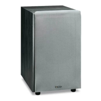
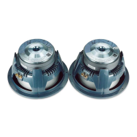
Details on identifying and specific parts for different revision versions of the subwoofer.

General Specifications

Detailed Specifications

Controls and Their Function

Connection Methods

Operation

Setting and Adjusting Controls

Initial setup and guidance for volume and crossover frequency adjustment.

Crossover Frequency Adjustment

How to adjust the crossover frequency for optimal bass response with satellite speakers.

Usage Tips and Room Placement

Recommendations for room placement and advice on tone controls.

Test Set Up and Procedures

General Function and Driver Tests

Procedures for testing basic functions, driver resistance, and audio performance.

Sweep Function and Noise Testing

Testing for rattles or noises using a sweep generator across a frequency range.

Amplifier Section Tests

Power Amplifier Testing Procedures

Resistance, power-up, DC operation, and switching frequency tests for the power amp.

Pre-Amplifier Testing Procedures

Input sensitivity, low-pass filter, and LED indicator tests for the pre-amp section.

Power Amplifier Test Flow Chart

Service Bulletin: Solder Joint Issues

Troubleshooting Solder Connections

Steps to re-solder connections to fix "Dead, No Output, or Motorboating" issues.

Service Bulletin: C6 Capacitor Failure

Capacitor C6 Replacement Procedure

Instructions to order and replace capacitor C6 for "no output" complaints.

Service Bulletin: Fuse Blowing Issues

Fuse and Transformer Replacement Guide

Addresses repeated fuse blowing by replacing fuse F1 and transformer T1.

Tech Tips: Front Panel Service

Front Panel Disassembly Procedure

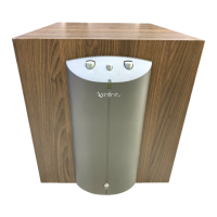
Step-by-step guide to access and service front panel components.

Amplifier Assembly Exploded View

Packing and Cabinet Parts

PCB Layouts (PLAIN 5)

PLAIN 5 Component Side Trace

Diagram showing component placement on the PLAIN 5 PCB.

PLAIN 5 Solder Side Trace Layer

Diagram showing the solder side trace layout of the PLAIN 5 PCB.

PCB Layouts (PLAIN 5.1)

PLAIN 5.1 Component Side Trace

Diagram showing component placement on the PLAIN 5.1 PCB.

PLAIN 5.1 Solder Side Trace Layer

Diagram showing the solder side trace layout of the PLAIN 5.1 PCB.

Integrated Circuit and Transistor Diagrams

Schematic Diagram - Part 1

Schematic Diagram - Part 2

Power Amp Module and Parts List

Power Amp Module PCB Layout (Rev C)

Circuit Board Layouts (Rev C - Part 1)

Circuit Board Layouts (Rev C - Part 2)

Schematic Diagram (Rev C)

Power Amp Module Schematic (Rev C)

Power Amp Module Schematic Details (Rev C)

Related product manuals