Do you have a question about the Infinity HPS250 and is the answer not in the manual?
Safety precautions for servicing the amplifier, including potential hazardous voltage.
Key technical specifications including power, frequency, phase, driver size, inputs/outputs, and dimensions.
Gain, Phase, Crossover controls for audio adjustment and tuning.
LED indicator and the main power switch.
Low Level Inputs, AC Plug, High Level Inputs, and Fuse.
Diagram illustrating the signal path through the subwoofer's internal stages.
Identifies major components like Input Buffer, Gain Stage, Overdrive Management, and Output stages.
Lists and visually identifies all parts of the subwoofer cabinet assembly.
Details part numbers and quantities for cabinet components.
Step-by-step instructions for safely removing the amplifier assembly.
Step-by-step instructions for safely removing the woofer from the cabinet.
Procedures for bias and audio performance tests.
Critical safety measures to follow when working on the amplifier.
Lists required equipment and shows connection diagram for testing.
Steps for testing basic operational functions of the unit.
Procedure for testing frequency response using a sweep generator.
Steps to test the driver's mechanical and electrical integrity.
Capacitors, diodes, transistors, resistors, and ICs for the power supply.
Components for the linear board, including capacitors, diodes, resistors, and ICs.
List of components for the high-level input board.
List of components for the line filter board.
Lists components for the LED board and general miscellaneous parts.
Lists components found exclusively on the 230V model.
Details the main carton and protective foam inserts for shipping.
Lists survey card, warranty card, owner's manual, and AC power cords.
Diagrams for TL084 Quad Op Amp and LM324N Quad Op Amp.
Diagram for the MOC3012 Optocoupler.
Diagram for the UC3842N PWM Controller.
Layout of components on the Power Supply PCB's component side.
Layout of components on the Power Supply PCB's solder side.
Layout of components on the Main PCB's component side.
Layout of components on the Main PCB's solder side.
Component and solder side views of the AC Power PCB.
Component side view of the Shield/LED PCB.
Component and solder side views of the HL Shield PCB.
Schematic for the Line Filter Board.
Schematic for the Low Level Input Board.
Schematic for the Shield/LED Board.
Schematic section covering Pre-Amp, Compressor, Gain, Limit Detect, Limiter.
Schematic section covering Bias, Rect Signal, Buck Regulators.
Schematic section covering Mute, OVP, Buckreg.
Part 1 of the power supply schematic, covering pulse width modulation and voltage regulation.
Part 2 of the power supply schematic, covering low-level regulators and voltage monitoring.
Schematic diagram for the High Level Input Board.
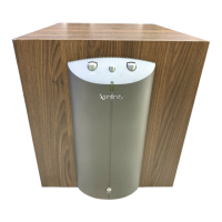
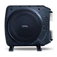
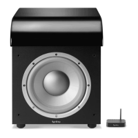
The Infinity HPS250 is a high-current powered subwoofer designed to enhance the low-frequency audio experience in a home entertainment system. It integrates an amplifier and a speaker driver into a single unit, providing powerful and controlled bass output.
The primary function of the HPS250 is to reproduce low-frequency sounds (bass) that are often difficult for main or satellite speakers to handle effectively. It acts as a dedicated bass speaker, taking a low-level or high-level audio signal, amplifying it, and driving a large woofer to produce deep, impactful bass. The subwoofer is designed to seamlessly integrate with existing audio systems, complementing the sound produced by other speakers rather than overpowering them.
The HPS250 features a sophisticated internal architecture that includes an input buffer, gain stage, and overdrive management, ensuring clean and powerful audio reproduction. It incorporates both high-pass and low-pass filters to precisely control the frequency range it reproduces, allowing for a smooth transition between the subwoofer and the main speakers. A phase switch is also included to adjust the relative polarity of the subwoofer, which is crucial for achieving optimal sound integration and avoiding phase cancellation with other speakers in the room. The bridged output configuration of the amplifier ensures efficient power delivery to the woofer.
The HPS250 offers several user-adjustable controls and input/output options to facilitate its integration and optimize its performance within various audio setups.
The design emphasizes user convenience, allowing for flexible connectivity options to accommodate different home audio systems. The controls are intuitively placed for easy access and adjustment, enabling users to tailor the subwoofer's performance to their specific listening environment and preferences.
The HPS250 is designed with serviceability in mind, providing clear procedures for disassembly and testing, which are essential for troubleshooting and repair.
These detailed maintenance and testing procedures allow for effective diagnosis and repair, ensuring the longevity and optimal performance of the HPS250. The modular design, with separate boards for power supply, main processing, AC power, shield/LED, and high-level input, simplifies component replacement and troubleshooting.
| Type | Powered Subwoofer |
|---|---|
| Power Output | 250 Watts RMS |
| Frequency Response | 30Hz - 150Hz |
| Impedance | 8 Ohms |
| Sensitivity | 90dB |
| Enclosure Type | Bass Reflex |
| Driver Size | 12 inches |