Do you have a question about the Infinity Classia Series and is the answer not in the manual?
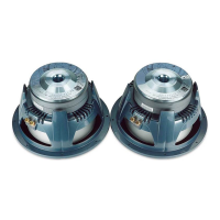
Lists all part numbers and descriptions for the subwoofer assembly.
Details the controls and inputs on the rear panel of the subwoofer.
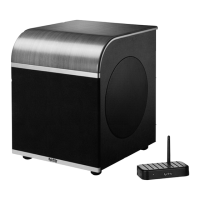
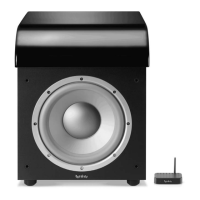
Identifies the connection points for the wireless transmitter module.
Step-by-step guide for connecting the subwoofer wirelessly.
Step-by-step guide for connecting the subwoofer via wired connection.
Instructions for powering the unit on and its automatic standby modes.
Initial setup, LED status, and adjusting subwoofer volume for optimal sound.
Guidance on setting phase and crossover controls for sound tuning.
Instructions for changing wireless channels to avoid interference.
Lists all part numbers and descriptions for the transmitter assembly.
Lists necessary tools and components for performing tests.
Step-by-step procedure for testing the subwoofer's basic functions.
Procedure for testing without the wireless transmitter.
Procedures for sweep testing and checking driver resistance.
Schematic diagram for the Wireless PCB.
Schematic diagram for the Pre-Amplifier PCB.
Schematic diagram for the Power Amplifier PCB.
Component placement diagram for a PCB.
Component placement diagram for a PCB.
List of resistors and capacitors for the main power supply PCB.
List of capacitors used in the device.
List of transistors, diodes, and ICs used in the device.
List of miscellaneous electronic components.
List of transistors, diodes, and ICs used in the device.
List of miscellaneous electronic components.
List of components for the input/preamp PCB.
List of capacitors used in the device.
List of transistors, diodes, and ICs used in the device.
List of components for the input/preamp PCB.
List of transistors, diodes, and ICs used in the device.
List of miscellaneous electronic components.
List of resistors and capacitors for the RABOS PCB.
List of parts for the wireless receiver PCB.
Recommended replacement module for the Class D PCB.
List of components for the Class D PCB assembly.
List of transistors, diodes, and ICs used in the device.
List of miscellaneous and mechanical components.
List of miscellaneous and mechanical components.
Provides a description of the LM5008 regulator's features.
Lists the key features of the LM5008 regulator.
Details the function of each pin on the LM5008 regulator.
Shows the typical application circuit and block diagram for the LM5008.
Lists the features of the 74HC/HCT165 shift register.
Provides a general description of the 74HC/HCT165 shift register.
Details the function of each pin on the 74HC/HCT165 shift register.
Illustrates the functional operation of the 74HC/HCT165 shift register.
Lists the key features of the CS4340 stereo DAC.
Provides a description of the CS4340 stereo DAC's capabilities.
Details the function of each pin on the CS4340 DAC.
Summarizes the features of the STM809/810/811/812 reset circuit ICs.
Lists the available device options and package types for the reset ICs.
Provides a summary description of the reset circuit devices.
Illustrates the available package types for the reset ICs.
Logic diagrams for STM809/810 and STM811/812 reset circuits.
Block diagram illustrating the functionality of the reset circuit ICs.
Lists the key features of the WHAM2 wireless audio solution.
Provides a general description of the WHAM2 wireless audio module.
Details the pin assignments and functions for the WHAM2 receiver.
Diagram showing the component layout for the WHAM2 transmitter.
Diagram showing the component layout for the WHAM2 receiver.
Circuit diagrams for TL072 and TL074 operational amplifiers.
Circuit diagrams for various transistors and MOSFETs.