Hardware Components
For the Infoblox-2000-A Appliance 7
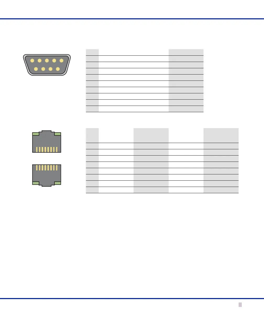
Figure 4 Connector Pin Assignments
21 345
6789
213465
7
8
786534
2
1
DB-9 Connector Pin Assignments
RJ-45 Connector Pin Assignments
Pin 10Base-T
100Base-T
Signal
1000Base-T
Signal
T568A
Straight-Through
Wire Color
T568B
Straight-Through
Wire Color
1Transmit + BI_DA+ White/Green White/Orange
2Transmit - BI_DA- Green Orange
3Receive + BI_DB+ White/Orange White/Green
4 (not used) BI_DC+ Blue Blue
5 (not used) BI_DC- White/Blue White/Blue
6Receive - BI_DB- Orange Green
7 (not used) BI_DD+ White/Brown White/Brown
8 (not used) BI_DD- Brown Brown
Male DB-9 Console Port
RJ-45 Ethernet Ports
Pin Signal Direction
1 (not used)
2Receive Input
3Transmit Output
4DTE Ready Output
5 Ground —
6 DCE Ready Input
7 RTS (Request to Send) Output
8 CTS (Clear to Send) Output
9 (not used)
Legend: BI_D = bidirectional; A, B, C, D = wire pairings
(Looking into the console
port on an Infoblox
appliance)
(Looking into RJ-45
Ethernet ports on an
Infoblox appliance)
 Loading...