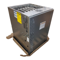
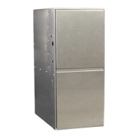
Do you have a question about the Ingersoll-Rand A951X080BU4SAB and is the answer not in the manual?
Covers general hazards like fire, explosion, shock, and CO poisoning.
Details on propane explosion, electrical shock, and CO poisoning hazards.
Hazards related to flammable vapors, gas connectors, and high voltage parts.
Procedure for shutting off gas supply during overheating.
Essential safety practices, precautions, and general installation guidelines.
Requirements for furnace location, clearances, and site preparation.
Diagrams and notes for gas piping connections on upflow and downflow furnaces.
Diagrams for horizontal gas piping connections on left and right orientations.
Procedure for checking combustion and input rate using gas flow tables.
Step-by-step instructions for adjusting gas valve manifold pressure.
Instructions for positive-pressure venting systems and material requirements.
Options to prevent condensation in combustion air intake piping.
Guidelines for direct and nondirect vent termination and applications.
Requirements for adequate airflow for combustion, ventilation, and dilution.
Standards for air duct systems, flexible connections, and noise reduction.
General guidelines for return duct connections on S-Series furnaces.
Typical upflow return air filter installation guidelines and filter sizes.
Wiring diagram for single stage heating thermostat, AC, or heat pump.
Provisions to prevent winter freeze-up of condensate drain lines.
Procedures for adjusting and checking control and safety switches.
Approved venting options for upflow and horizontal left furnace models.
Approved venting options for horizontal right furnace models.
Approved venting options for downflow furnace models.
Overview of the Integrated Furnace Control menu for single stage operation.
Explanation of system status codes displayed on the IFC.
Table showing CFM and Watts at different static pressures and tap settings.
List of IFC menu options and corresponding alarm error codes.
Detailed operational sequence for gas heating mode.
Detailed operational sequence for cooling and heat pump modes.
| Model Number | A951X080BU4SAB |
|---|---|
| Category | Furnace |
| Input BTU | 80, 000 |
| Phase | 1 |
| Ignition Type | Hot Surface Ignition |
| Brand | Ingersoll Rand |
| AFUE Rating | 80% |
| Blower Speed | Variable |


 Loading...